將要如何追查
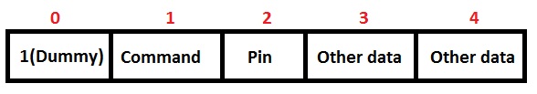
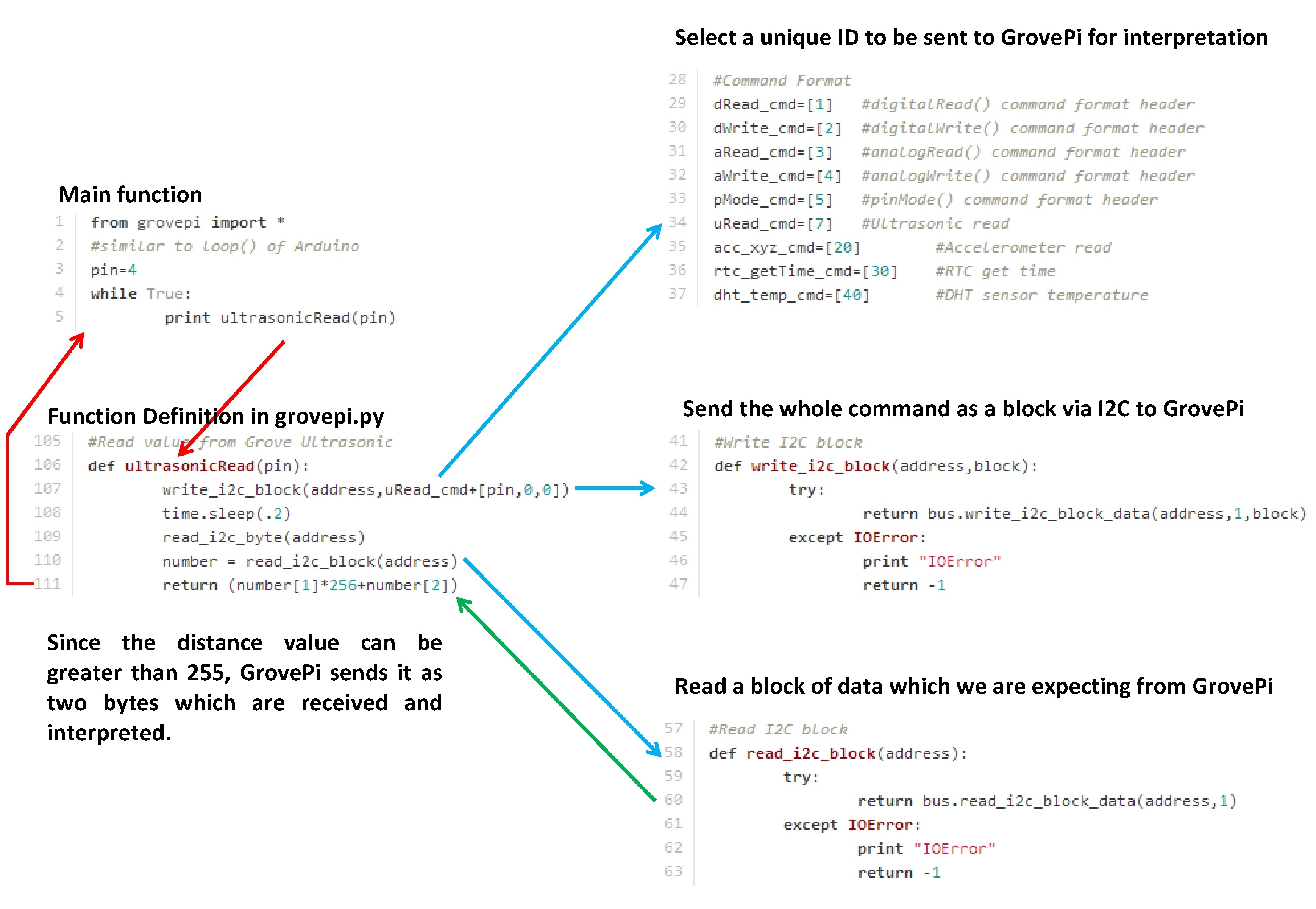
若是考以不同『裝置組合』,為什麼『超聲波測距儀』 Ultrasonic Ranger 與『繼電器』 Relay 分接『三、七』可以!但是『二、八』卻不行的呢?
import time
import grovepi

relay = 8

ultrasonic_ranger = 2

grovepi.pinMode(relay,"OUTPUT")

time.sleep(0.1)

grovepi.digitalWrite(relay,1)

time.sleep(0.5)

while True:
    try:

# 因派生二、三『 print 』語法不同之相容寫法。
        print (grovepi.ultrasonicRead(ultrasonic_ranger))

        time.sleep(0.1)

    except IOError:
        print ("Error")
。一個簡單如此的程式!又怎麼會出錯的呢?既然是寫 W!o+ 的『小伶鼬工坊演義』,總該採納 Mrphs 是怎麼說的哩!!恍恍惚惚中,或是這麼講的吧︰ W!o+ 認為『單獨』與『共聚』物件情況,有很大的不同。縱使彼此可以排除『干擾性』,還有『同時性』和『共時性』的難題,這大部分發生於『資源性』之競奪領域。若是因『時序性』之問題引起,它在『通訊規範』的設計上尤其重要。大自然春暖花開固然花花無礙,社會上洛陽紙貴可就買不著的了。這些終究還是得用『實驗』來『確立』的事務。……
於是努力地嘗試改寫 GrovePi V1.2.5之 韌體,啟動 GrovePi 的Serial 通訊埠,
void setup()
{
# 打開序列通訊埠
    Serial.begin(9600);         // start serial for output
    Wire.begin(SLAVE_ADDRESS);

    Wire.onReceive(receiveData);
    Wire.onRequest(sendData);
        attachInterrupt(0,readPulseDust,CHANGE);
}

    //Ultrasonic Read
    else if(cmd[0]==7)
    {
      pin=cmd[1];
      pinMode(pin, OUTPUT);
      digitalWrite(pin, LOW);
      delayMicroseconds(2);
      digitalWrite(pin, HIGH);
      delayMicroseconds(5);
      digitalWrite(pin,LOW);
      pinMode(pin,INPUT);
      dur = pulseIn(pin,HIGH);
      RangeCm = dur/29/2;
      b[1]=RangeCm/256;
      b[2]=RangeCm%256;
# 序列埠輸出傳回值
      Serial.print(b[1]);
      Serial.print(", ");
      Serial.print(b[2]);
      Serial.print(", ");
    }

void receiveData(int byteCount)
{
    while(Wire.available())
    {
      if(Wire.available()==4)
      {
        flag=0;
        index=0;
                run_once=1;
      }
        cmd[index++] = Wire.read();
    }
# 序列埠輸出當下指令
    Serial.print("Command ");
    Serial.println(cmd[0]);
}
,以備『實驗』、『探索』、『除錯』之所需。然後用『USB TTL RS232 轉換器』接回樹莓派︰
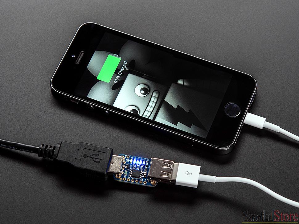
Adafruit USB Power Gauge Mini-Kit

USB TTL RS232 轉換器
後來作者發現 Adafruit 有一款 TTL RS232 界面之迷你的『 USB 埠傳輸功率量測』裝置,如果再加上『USB TTL RS232 轉換器』可以構成一套既便宜又好用的『功率量測』系統。假使輔之以『測試軟體』,可以『自動紀錄』任何一個『 USB 裝置』在各種『工作樣態』下的『功率消耗』。由於它的『量測範圍』可以及於『5V 2A』,因此即使一整個『樹莓派系統』的『消耗功率』大體也可以這麼度量。再者,這個裝置的『資料』輸出格式十分簡單易讀,也就很容易寫『程式』來作『量測數據』處理。在此列出兩種『 USB DVD 讀寫裝置』之『操作狀態』下的消耗功率︰
─── 摘自《音樂播放器之 CD 轉成 mp3《三》上》
再用『已改寫』的 API 測試,初步之驗證結果如下︰
【在派生二解譯器中執行】
隨意連接五個派生命名裝置
Grove – Rotary Angle Sensor ︰ potentiometer A0
Grove – LED Socket Kit ︰ led D5
Grove – Relay ︰ relay D8
Grove – Relay ︰ power D7
Grove – Ultrasonic Ranger ︰ ultrasonic_ranger D4
# 關閉電源,重新開機。確定 Arduino 在 Hard Reset 狀態。 pi@raspberrypi ~/examplecat /dev/ttyUSB0 Command 7 0, 198, 1, 196, 1, 196, 1, 196, 1, 196, 1, 196, 1, 196, Command 7 1, 194, Command 3 Command 3 Command 3 Command 3 Command 7 0, 198, 0, 198, 0, 198, 0, 198, 0, 198, 0, 198, 0, 198, 0, 197, 0, 198, 0, 198, 0, 198, 0, 198, 0, 198, 0, 198, Command 7 0, 194, Command 7 0, 197, 0, 198, 0, 198, 0, 197, 0, 197, 0, 198, 0, 198, 0, 198, 0, 197, 0, 198, 0, 198, 0, 198, 0, 198, 0, 197, Command 7 0, 194, Command 3 Command 3 Command 2 Command 5 Command 2 Command 2 Command 5 Command 4 Command 4 Command 3 Command 3 Command 7 0, 198, 0, 198, 0, 198, 0, 198, 0, 198, 0, 198, 0, 198, 0, 198, 0, 198, 0, 198, 0, 198, 0, 198, 0, 198, 0, 198, Command 7 0, 194, Command 5 Command 2 Command 7 0, 197, 0, 197, 0, 197, 0, 197, 0, 198, 0, 198, 0, 197, 0, 197, 0, 197, 0, 198, 0, 198, 0, 197, 0, 197, 0, 197, Command 7 0, 194, Command 2