傳說愛因斯坦幼年覺得『畢氏定理』  太神奇!怎可能是真的呢?因此畫了許多大大小小、各式各樣的『直角三角形』,一一用『尺』丈量,決定實證『斜邊平方等於兩股平方和』之幾何推論??終究得折服於親手所作數值計算的結果了!!
假使從『陽燧照物』來看東西方古來『觀物論事』取向之異同
《周禮‧秋官司寇》
司烜氏:掌以夫遂取明火於日,以鑒取明水於月,以共祭祀之明粢、明燭,共明水。凡邦之大事,共墳燭庭燎。中春,以木鐸修火禁于國中。軍旅,修火禁。邦若屋誅,則為明竁焉。
《夢溪筆談》卷三‧辯證一
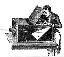
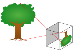
陽燧照物皆倒,中間有礙故也。算家謂之“格術”。如人搖櫓,臬為之礙故也。若鳶飛空中,其影隨鳶而移,或中間為窗隙所束,則影與鳶遂相違,鳶東則影西,鳶西則影東。又如窗隙中樓塔之影,中間為窗所束,亦皆倒垂,與陽燧一也。陽燧面窪,以一指迫而照之則正;漸遠則無所見;過此遂倒。其無所見處,正如窗隙、櫓臬、腰鼓礙之,本末相格,遂成搖櫓之勢。故舉手則影愈下,下手則影愈上,此其可見。陽燧面窪,向日照之,光皆聚向內。離鏡一、二寸,光聚為一點,大如麻菽,著物則火發,此則腰鼓最細處也。豈特物為然,人亦如是,中間不為物礙者鮮矣。小則利害相易 ,是非相反;大則以已為物,以物為已。不求去礙,而欲見不顛倒 ,難矣哉!《酉陽雜俎》謂“海翻則塔影倒”,此妄說也。影入窗隙則倒,乃其常理。
。這本《夢溪筆談》
是中國科學技術史上的重要文獻,百科全書式的著作,英國科學史家李約瑟稱讚本書為「中國科學史上的座標」。
實已說明『觀物』與『文不文』無關,『科學』之『辯證精神』是古今中外相通的。若說到表達語言的『文白問題』,或許只消嘗試讀一讀牛頓之《 Philosophiæ Naturalis Principia Mathematica 》的拉丁文『原著』或是『英譯本』,那就自問也可自答的吧。
─── 摘自《《派生》 Python 作坊【丁】陽燧月鑑》
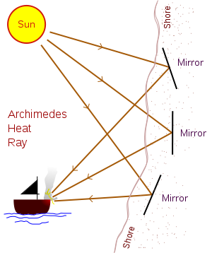
阿基米德『焦光』
Heat ray
Archimedes may have used mirrors acting collectively as a parabolic reflector to burn ships attacking Syracuse. The 2nd century AD author Lucian wrote that during the Siege of Syracuse (c. 214–212 BC), Archimedes destroyed enemy ships with fire. Centuries later, Anthemius of Tralles mentions burning-glasses as Archimedes’ weapon.[32] The device, sometimes called the “Archimedes heat ray“, was used to focus sunlight onto approaching ships, causing them to catch fire.
This purported weapon has been the subject of ongoing debate about its credibility since the Renaissance. René Descartes rejected it as false, while modern researchers have attempted to recreate the effect using only the means that would have been available to Archimedes.[33] It has been suggested that a large array of highly polished bronze or copper shields acting as mirrors could have been employed to focus sunlight onto a ship. This would have used the principle of the parabolic reflector in a manner similar to a solar furnace.
A test of the Archimedes heat ray was carried out in 1973 by the Greek scientist Ioannis Sakkas. The experiment took place at the Skaramagas naval base outside Athens. On this occasion 70 mirrors were used, each with a copper coating and a size of around five by three feet (1.5 by 1 m). The mirrors were pointed at a plywood mock-up of a Roman warship at a distance of around 160 feet (50 m). When the mirrors were focused accurately, the ship burst into flames within a few seconds. The plywood ship had a coating of tar paint, which may have aided combustion.[34] A coating of tar would have been commonplace on ships in the classical era.[d]
In October 2005 a group of students from the Massachusetts Institute of Technology carried out an experiment with 127 one-foot (30 cm) square mirror tiles, focused on a mock-up wooden ship at a range of around 100 feet (30 m). Flames broke out on a patch of the ship, but only after the sky had been cloudless and the ship had remained stationary for around ten minutes. It was concluded that the device was a feasible weapon under these conditions. The MIT group repeated the experiment for the television show MythBusters, using a wooden fishing boat in San Francisco as the target. Again some charring occurred, along with a small amount of flame. In order to catch fire, wood needs to reach its autoignition temperature, which is around 300 °C (570 °F).[35][36]
When MythBusters broadcast the result of the San Francisco experiment in January 2006, the claim was placed in the category of “busted” (or failed) because of the length of time and the ideal weather conditions required for combustion to occur. It was also pointed out that since Syracuse faces the sea towards the east, the Roman fleet would have had to attack during the morning for optimal gathering of light by the mirrors. MythBusters also pointed out that conventional weaponry, such as flaming arrows or bolts from a catapult, would have been a far easier way of setting a ship on fire at short distances.[37]
In December 2010, MythBusters again looked at the heat ray story in a special edition entitled “President’s Challenge”. Several experiments were carried out, including a large scale test with 500 schoolchildren aiming mirrors at a mock-up of a Roman sailing ship 400 feet (120 m) away. In all of the experiments, the sail failed to reach the 210 °C (410 °F) required to catch fire, and the verdict was again “busted”. The show concluded that a more likely effect of the mirrors would have been blinding, dazzling, or distracting the crew of the ship.[38]
Archimedes may have used mirrors acting collectively as a parabolic reflector to burn ships attacking Syracuse.
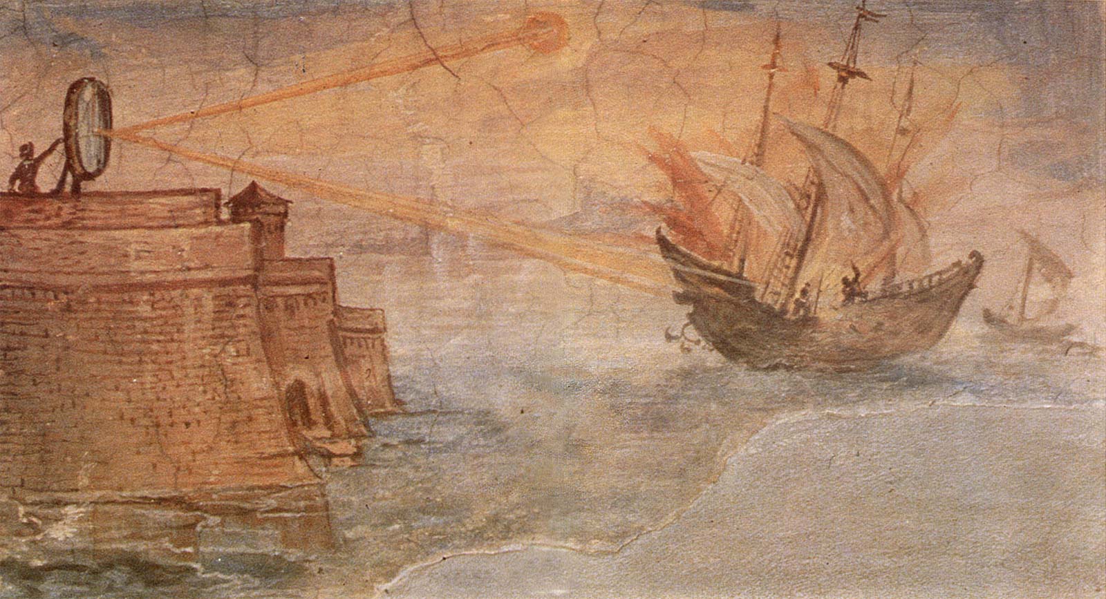
Artistic interpretation of Archimedes’ mirror used to burn Roman ships. Painting by Giulio Parigi.
或許終落『事理』上之『定性類比』與『定量歸結』的耶??不過就『實用』目的而言『焦點』則一也!!
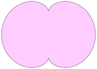
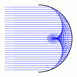
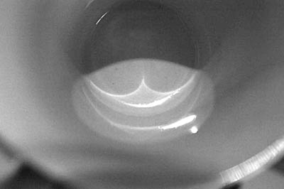
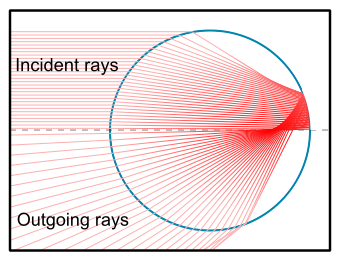
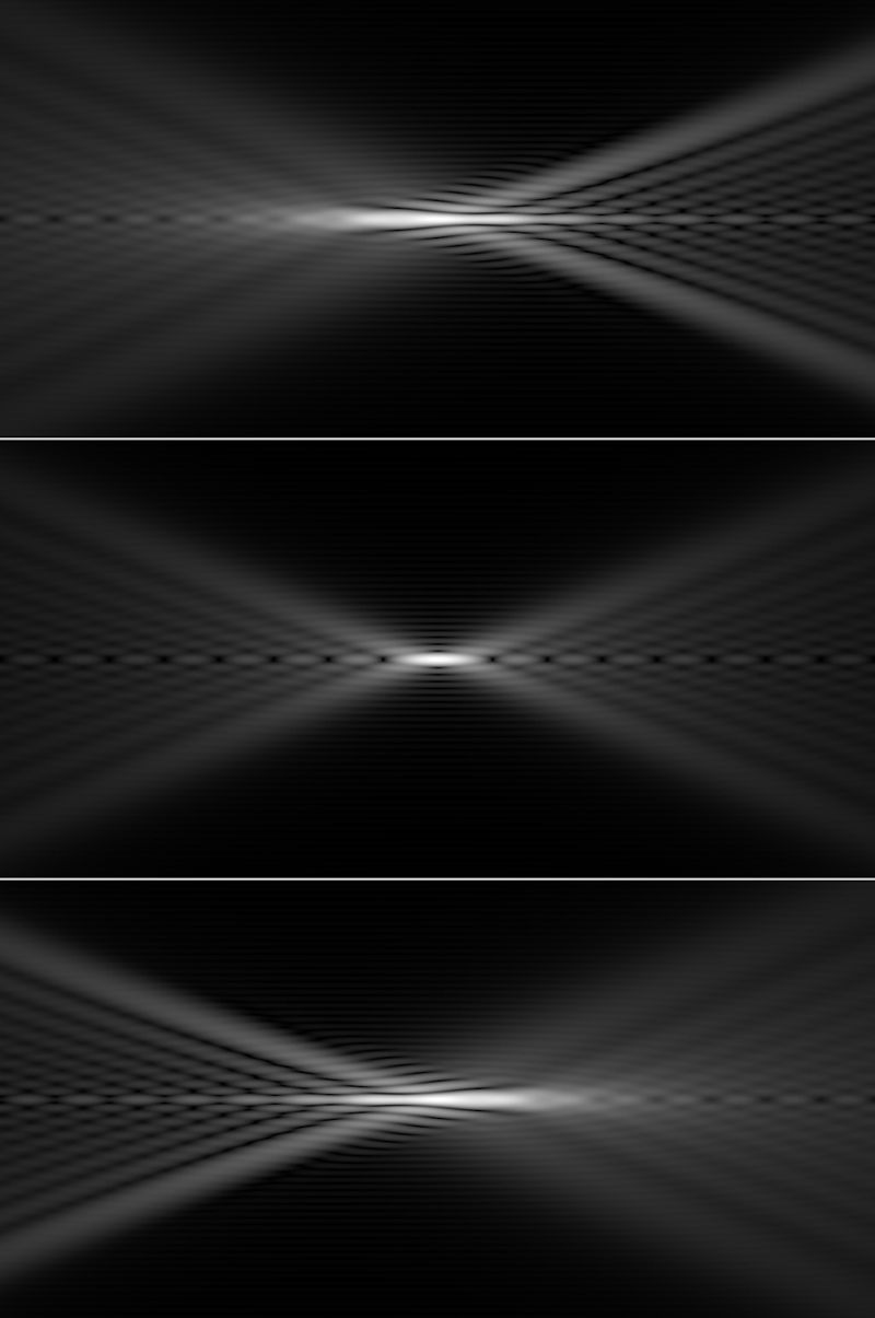
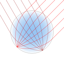
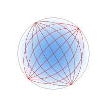
既然已經知道『波前』之『反射』或『折射』交匯可形成 Caustic ── 包絡線 ──
Envelope (mathematics)
In geometry, an envelope of a family of curves in the plane is a curve that is tangent to each member of the family at some point. Classically, a point on the envelope can be thought of as the intersection of two “adjacent” curves, meaning the limit of intersections of nearby curves. This idea can be generalized to an envelope of surfaces in space, and so on to higher dimensions.
Envelope of a family of curves
Let each curve Ct in the family be given as the solution of an equation ft(x, y)=0 (see implicit curve), where t is a parameter. Write F(t, x, y)=ft(x, y) and assume F is differentiable.
The envelope of the family Ct is then defined as the set of points for which

for some value of t, where 
Note that if t and u, t≠u are two values of the parameter then the intersection of the curves Ct and Cu is given by

or equivalently

Letting u→t gives the definition above.
An important special case is when F(t, x, y) is a polynomial in t. This includes, by clearing denominators, the case where F(t, x, y) is a rational function in t. In this case, the definition amounts to t being a double root of F(t, x, y), so the equation of the envelope can be found by setting the discriminant of F to 0.
For example, let Ct be the line whose x and y intercepts are t and 1−t, this is shown in the animation above. The equation of Ct is

or, clearing fractions,

The equation of the envelope is then

Often when F is not a rational function of the parameter it may be reduced to this case by an appropriate substitution. For example if the family is given by Cθ with an equation of the form u(x, y)cosθ+v(x, y)sinθ=w(x, y), then putting t=eiθ, cosθ=(t+1/t)/2, sinθ=(t-1/t)/2i changes the equation of the curve to

or

The equation of the envelope is then given by setting the discriminant to 0:

or

Alternative definitions
- The envelope E1 is the limit of intersections of nearby curves Ct.
- The envelope E2 is a curve tangent to all of the Ct.
- The envelope E3 is the boundary of the region filled by the curves Ct.
Then 


───
何不援用中外之長,假借『SymPy』工具,『定性、定量』驗證個仔細乎??!!
pi@raspberrypi:~t
E
\alpha
y = x^2
y = 2x
\overline{EB}
y - t^2 = 2t(x - t)
x
y=0
x = \frac{t}{2}
B
\overline{AD}
\tan ( \alpha ) = \frac{\frac{t}{2}}{t^2} = \frac{1}{2t}
\overline{EF}
\tan ( \frac{\pi}{2} - 2 \alpha ) = \cdots = \frac{4 t^2 -1}{4t}
y - t^2 = \frac{4 t^2 -1}{4t} (x-t)
y
x=0
t
y = \frac{1}{4}
{(4y-1)}^2 - 16 x^2 = 0$
這條方程式。實是兩條直線,相交於『焦點』。
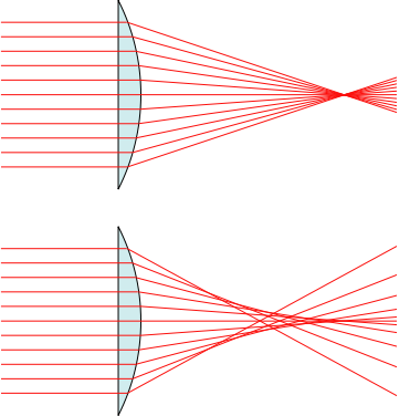
果然『高斯光學』的『部份球面』例無虛發,事理不二矣!!!
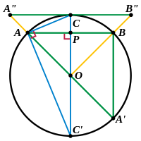
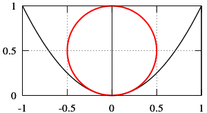
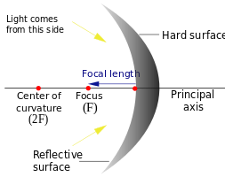
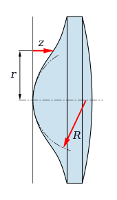
Focal length and radius of curvature at the vertex
mage is inverted. A"B" is x-axis. C is origin. O is centre. A is (x,y). OA=OC=R. PA=x. CP=y. OP=(R-y). Other points and lines are irrelevant for this purpose.
The radius of curvature at the vertex is twice the focal length. The measurements shown on the above diagram are in units of the latus rectum, which is four times the focal length.
Consider a point
on a circle of radius
and with centre at the point
The circle passes through the origin. If the point is near the origin, the Pythagorean Theorem shows that:


But, if 


-
.....(Equation 1)
Compare this with the parabola:
......(Equation 2)
which has its vertex at the origin, opens upward, and has focal length 
Equations 1 and 2 are equivalent if 
Corollary
A concave mirror which is a small segment of a sphere behaves approximately like a parabolic mirror, focusing parallel light to a point which is midway between the centre and the surface of the sphere.
───
 之
之 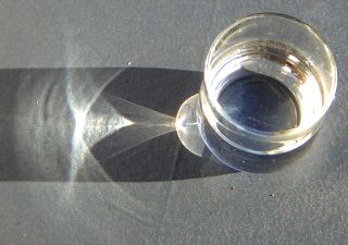
 ) to glass (
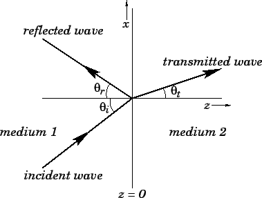
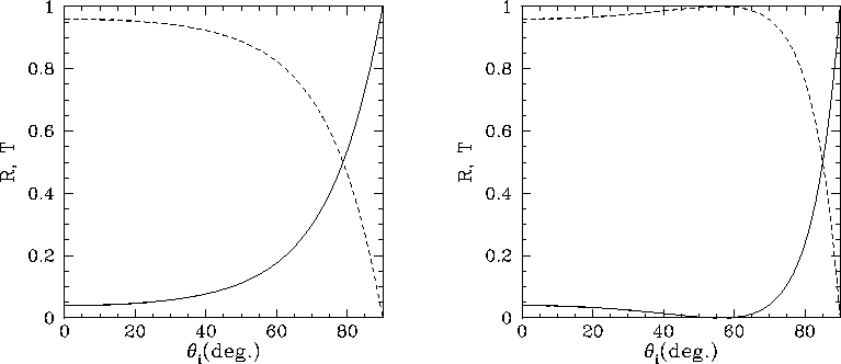
 ). The left-hand panel shows the wave polarization for which the electric field is parallel to the boundary, whereas the right-hand panel shows the wave polarization for which the magnetic field is parallel to the boundary. In general, it can be seen that the coefficient of reflection rises, and the coefficient of transmission falls, as the angle of incidence increases. Note, however, that for the second wave polarization there is a particular angle of incidence, know as the Brewster angle, at which the reflected intensity is zero. There is no similar behaviour for the first wave polarization.


 圖中『空氣、玻璃』界面為例,僅以『近軸角度』
  為界。依據『
 ,可得『折射角』
  。所以
。所以 ,可知『反射比率』約莫
 也,故而難得多次反射影響成像乎!!
 ,那麼
,那麼
 之世界哩??!!
 of the material composing the lens falls from 2 at its center to 1 at its surface (or equivalently, the
  falls from
  to 1), according to
 .
.


 的公式:
的公式:
 是焦距,
是焦距, 是光的
是光的
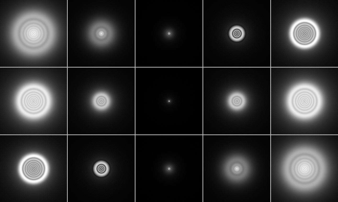
 , is much smaller than the resolving power of the telescope:
 ,
, is the telescope diameter.


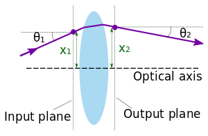
 at the input plane and
  when the ray arrives at the output plane.