致 PhET 之愛好者︰

最近樹莓派基金會之桌面環境換了新妝

PiXEL

pixel


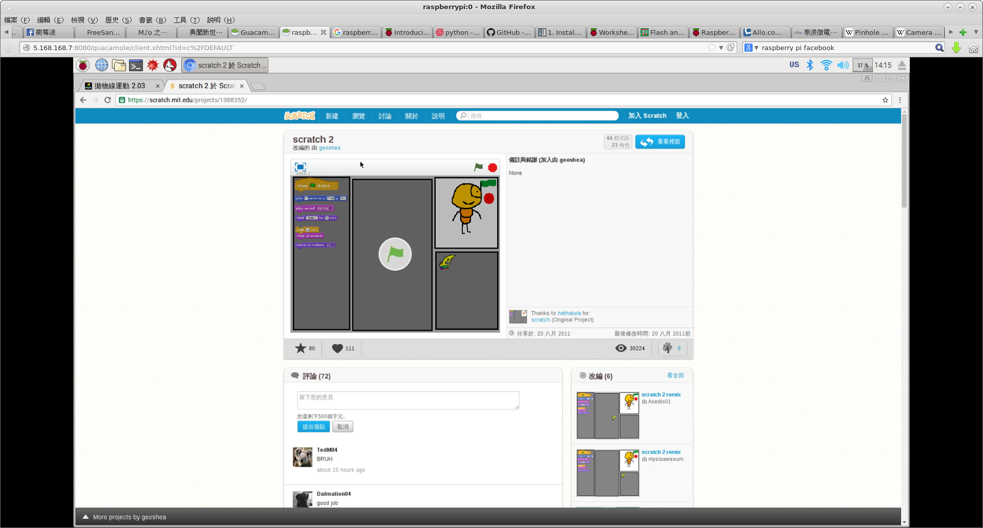
由於 MIT 的 scratch 2.0

scratch-2


需要使用 Adobe Flash 。因此預設的 Google Chrome 正式支援了

Flash Player now available for Chromium

by spl23 » Tue Oct 11, 2016 5:52 pm

I’m pleased to announce that Adobe’s Flash Player is now available for Chromium on the Pi. If you are running PIXEL, “sudo apt-get update” followed by “sudo apt-get dist-upgrade” will install the Flash Player binary ready for use in Chromium.

Flash is blocked by default – if you access a web site which wishes to use Flash, you will be prompted to right-click to enable the Flash player.

The Flash Player only works on ARMv7 platforms, so is only available on Pi 2 and Pi 3; it won’t work on Pi 0 or Pi 1.

──

by DNPNWO » Tue Oct 11, 2016 6:29 pm

What version of Flash is installed? Current for Chrome/Chromium browser appears to be v23.

Adobe Flash Player – Version: 23.0.0.166
Shockwave Flash 23.0 r0
Name: Shockwave Flash
Description: Shockwave Flash 23.0 r0
Version: 23.0.0.166

………


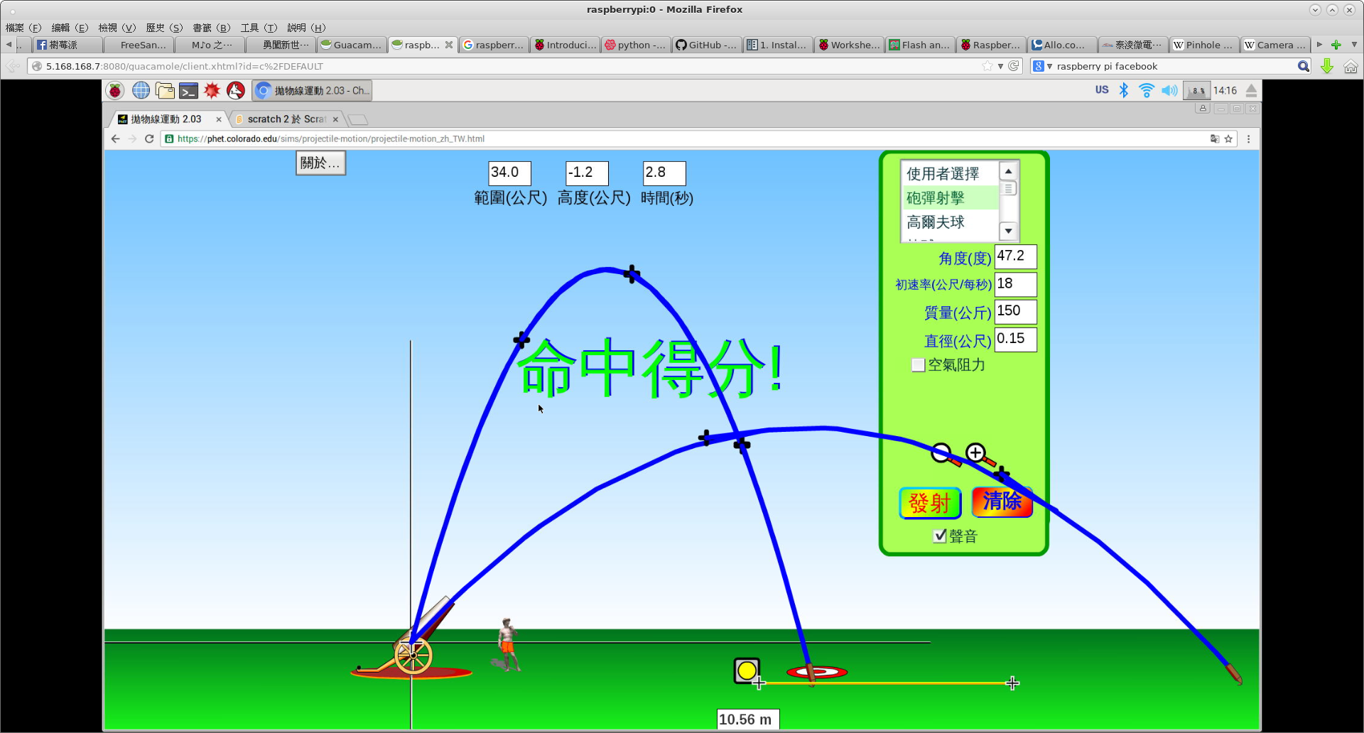
此舉也為 PhET Flash 版之科學與數學的互動式模擬教學打開了大門

phet


特享 PhET 廣大愛好者☆


樹莓派相機︰ RaspiCAM Clone !

『克隆』 Clone 一詞由來久已︰

Clone (computing)

In computing, a clone is a hardware or software system that is designed to function in the same way as another system.[1] A specific subset of clones are Remakes (or Remades), which are revivals of old, obsolete, or discontinued products.


或早成為 □○『相容性』之代表,所謂『白牌機』的世界。

Hardware clones

When IBM announced the IBM PC in 1981, other companies such as Compaq decided to offer clones of the PC as a legal reimplementation from the PC’s documentation or reverse engineering. Because most of the components, except the PC’s BIOS, were publicly available, all Compaq had to do was reverse-engineer the BIOS. The result was a machine with better value than the archetypes that the machines resembled. The use of the term “PC clone” to describe IBM PC compatible computers fell out of use in the 1990s; the class of machines it now describes are simply called PCs, but the early use of the term “clone” usually implied a higher level of compatibility with the original IBM PC than “PC-Compatible”, with (often Taiwanese) clones of the original circuit (and possibly ROMs) the most compatible (in terms of software they would run and hardware tests they would pass), while “legitimate” new designs such as the Sanyo MBC-550 and Data General One, while not infringing on copyrights and adding innovations, tended to fail some compatibility tests (such as its ability to run Microsoft Flight Simulator, or any software that bypassed the standard software interrupts and directly accessed hardware at the expected pre-defined locations, or – in the case of the MBC-550 for example, created diskettes which could not be directly interchanged with standard IBM PCs).

While the term has fallen mostly into commercial disuse, the term clone for PCs still applies to a PC made to entry-level or above standard (at the time it was made) which bears no commercial branding (e.g., Acer, IBM, HP, Dell). This includes, but is not limited to, PCs assembled by home users or Corporate IT Departments. (See also White box (computer hardware).)

There were many Nintendo Entertainment System hardware clones due to the popularity and longevity of the Nintendo Entertainment System.


開源之精神允許『複刻』︰

Fork (software development)

In software engineering, a project fork happens when developers take a copy of source code from one software package and start independent development on it, creating a distinct and separate piece of software. The term often implies not merely a development branch, but a split in the developer community, a form of schism.[1]

Free and open-source software is that which, by definition, may be forked from the original development team without prior permission without violating copyright law. However, licensed forks of proprietary software (e.g. Unix) also happen.


相信也歡迎『復制』的吧︰

Cameras for RaspberryPi

In order to meet the increasing need of Raspberry Pi compatible camera modules. The ArduCAM team now released series of camera modules both 5MP and 8MP for Raspberry Pi which is fully compatible with official one. They are divided into standard version, optimized optical performance vision, miniature size spy camera vision, NoIR vision which give user a much clear and sharp image compared to the official Pi camera, even provides the FREX and STROBE signals which can be used for multi-camera synchronize capture with proper camera driver firmware.

Raspberry Pi is a trademark of the Raspberry Pi Foundation

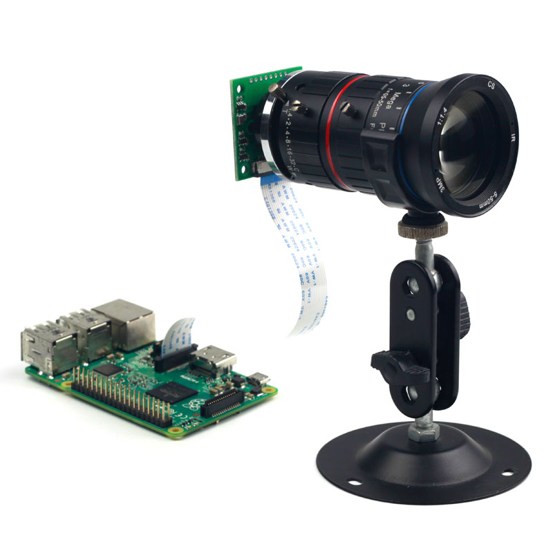
imx219-pi-camera-m12-7

CS mount zoom lens


如是使用者將有更多選擇的乎☆


樹莓派相機︰ 認識 RaspiCAM

無論打算作什麼相機應用,即便只是想玩玩而已,需要有個相機的吧。這裡匯總樹莓派基金會官方版 RaspiCAM 一些資料鍊結,方便有興趣的讀者參考。

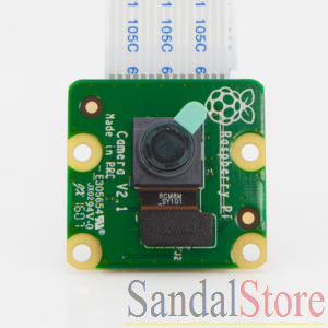
624_p_1461544114745


【硬體規格】

Camera Module

The Raspberry Pi Camera Module is an official product from the Raspberry Pi Foundation. The original 5-megapixel model was released in 2013, and an 8-megapixel Camera Module v2 was released in 2016. For both iterations, there are visible light and infrared versions.

Hardware specification

  Camera Module v1 Camera Module v2
Net price $25 $25
Size Around 25 × 24 × 9 mm  
Weight 3g  
Still resolution 5 Megapixels 8 Megapixels
Video modes 1080p30, 720p60 and 640 × 480p60/90 1080p30, 720p60 and 640 × 480p60/90
Linux integration V4L2 driver available V4L2 driver available
C programming API OpenMAX IL and others available OpenMAX IL and others available
Sensor OmniVision OV5647 Sony IMX219
Sensor resolution 2592 × 1944 pixels 3280 × 2464 pixels
Sensor image area 3.76 × 2.74 mm  
Pixel size 1.4 µm × 1.4 µm  
Optical size 1/4″  
Full-frame SLR lens equivalent 35 mm  
S/N ratio 36 dB  
Dynamic range 67 dB @ 8x gain  
Sensitivity 680 mV/lux-sec  
Dark current 16 mV/sec @ 60 C  
Well capacity 4.3 Ke-  
Fixed focus 1 m to infinity  
Focal length 3.60 mm +/- 0.01  
Horizontal field of view 53.50 +/- 0.13 degrees  
Vertical field of view 41.41 +/- 0.11 degrees  
Focal ratio (F-Stop) 2.9  

……


機構圖

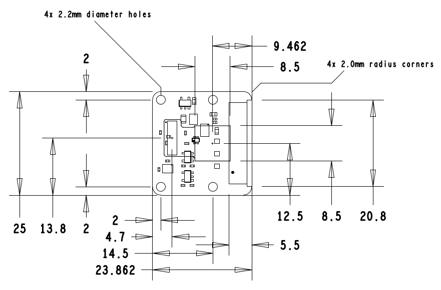
raspicam-m


【命令列應用程式】

Raspberry Pi Camera Module

This document describes the use of the three Raspberry Pi camera applications, as of January 8th 2015.

There are three applications provided: raspistill, raspivid, and raspistillyuv. raspistill and raspistillyuv are very similar and are intended for capturing images; raspivid is for capturing video.

All the applications are driven from the command line, and written to take advantage of the MMAL API which runs over OpenMAX. The MMAL API provides an easier to use system than that presented by OpenMAX. Note that MMAL is a Broadcom-specific API used only on Videocore 4 systems.

The applications use up to four OpenMAX (MMAL) components: camera, preview, encoder, and null_sink. All applications use the camera component; raspistill uses the Image Encode component; raspivid uses the Video Encode component; and raspistillyuv doesn’t use an encoder, and sends its YUV or RGB output directly from the camera component to file.

The preview display is optional, but can be used full-screen or directed to a specific rectangular area on the display. If preview is disabled, the null_sink component is used to ‘absorb’ the preview frames. The camera must produce preview frames even if these aren’t required for display, as they’re used for calculating exposure and white balance settings.

In addition, it’s possible to omit the filename option (in which case the preview is displayed but no file is written), or to redirect all output to stdout.

Command line help is available by typing just the application name in the command line.

Setting up

See Camera Setup.


【關掉 RaspiCAM LED 燈】

Disable camera led on Pi3

by Mettauk » Wed Mar 02, 2016 10:37 am

Apparently due to gpio changes on the Pi3 b disable_camera_led=1 no longer works.

Any ideas of anther way anyone?

───

by 6by9 » Wed Mar 02, 2016 11:54 am

disable_camera_led=1 on some clone camera boards fails – they used the LED line for other purposes. Sorry, can’t fix that one, and it just shows that reverse engineering is prone to mistakes.

It should work fine on a Pi3 – it just signals the driver to only toggle one of the GPIOs (which one is configured in the firmware dt-blob) instead of both.
https://github.com/raspberrypi/firmware … t-blob.dts hasn’t been updated as yet, but there appears to have been some changes made and the two camera GPIOs are on a GPIO expander.
It will mean that using PiCamera’s led function will fail as it doesn’t know about the Pi3. I’m not even sure if it is possible to get to those GPIOs from Linux – I’ll find out as I want to for getting raw access to the camera.

There’s an outside chance that the two GPIOs specified in the blob are swapped. That would also explain why it can’t find the camera if disable_camera_led is set.
I’ll email Pi Towers, but also try to have a look tonight (I haven’t actually powered my Pi3 up as yet!).

───

by 6by9 » Wed Mar 02, 2016 10:28 pm
It was an easy one. The config had swapped the two GPIOs, so I saw a brief camera LED flash when doing “vcgencmd get_camera” even though I’d set disable_camera_led=1.
A rebuild of the dt-blob.bin swapping the two lines and it works again even with disable_camera_led=1.For a couple of reasons that I won’t go into I can’t release that patched file – sorry. I’ll pass the patch across to Pi Towers and it should be available via sudo rpi-update fairly quickly.

……


LinuxTV V4L2 規範

Official V4L2 driver

by dom » Mon Dec 02, 2013 8:54 pm

EDIT: the default kernel includes v4l2 driver and the latest raspbian image includes the v4l2 utilities (like v4l2-ctl) so the initial steps can be skipped. Skip forward to the modprobe line.

rpi-update to get it. Consider this beta for now.

Some info is here (in linux tree):
https://github.com/raspberrypi/linux/bl … 5-v4l2.txt

You need a version 1.0 or later of v4l2-ctl, available from:
git://git.linuxtv.org/v4l-utils.git

i.e

sudo apt-get install autoconf gettext libtool libjpeg62-dev
cd v4l-utils
autoreconf -vfi
./configure
make
sudo make install

This takes about fifteen minutes.

You need to have camera enabled and sufficient gpu_mem configured (much like raspicam).
Some commands to get started:

# load the module
sudo modprobe bcm2835-v4l2

# viewfinder
v4l2-ctl –overlay=1 # enable viewfinder
v4l2-ctl –overlay=0 # disable viewfinder

# record video
v4l2-ctl –set-fmt-video=width=1920,height=1088,pixelformat=4
v4l2-ctl –stream-mmap=3 –stream-count=100 –stream-to=somefile.264

# capture jpeg
v4l2-ctl –set-fmt-video=width=2592,height=1944,pixelformat=3
v4l2-ctl –stream-mmap=3 –stream-count=1 –stream-to=somefile.jpg

# set bitrate
v4l2-ctl –set-ctrl video_bitrate=10000000

# list supported formats
v4l2-ctl –list-formats

In theory (some) apps that use V4L should work. Report back what does work and what doesn’t.
Thanks to Vincent Sanders at Collabora, and Luke Diamand and David Stevenson at Broadcom for working on this.

……


樹莓派相機︰ CSI-2 是什麼?

欲說 mipi alliance 之

Camera Interface Specifications

MIPI CSI-2 and MIPI CSI-3 are the successors of the original MIPI camera interface standard, and both standards continue to evolve. Both are highly capable architectures that give designers, manufacturers – and ultimately consumers – more options and greater value while maintaining the advantages of standard interfaces.

Evolving CSI-2 Specification

The bandwidths of today’s host processor-to-camera sensor interfaces are being pushed to their limits by the demand for higher image resolution, greater color depth and faster frame rates. But more bandwidth is simply not enough for designers with performance targets that span multiple product generations.

The mobile industry needs a standard, robust, scalable, low-power, high-speed, cost-effective camera interface that supports a wide range of imaging solutions for mobile devices.

The MIPI® Alliance Camera Working Group has created a clear design path that is sufficiently flexible to resolve not just today’s bandwidth challenge but “features and functionality” challenges of an industry that manufactures more than a billion handsets each year for a wide spectrum of users, applications and cost points.

Additional details are available in the MIPI Camera CSI-2 Specification Brief.


不得不先提及

智慧財產權

智慧財產權,又稱智慧財產權、智財權,是指智力創造成果:發明 文學藝術作品,以及商業中使用的符號、名稱、圖像和外觀設計。[1]智慧財產權可以分為工業產權與版權兩類,工業產權包括發明(專利)、商標、工業品外觀設計地理標誌,版權則包括文學和藝術作品。[1]

智慧財產權被概括為一切來自知識活動領域的權利,始於17世紀中葉法國學者卡普佐夫的著作,後由比利時法學家皮爾第所發展;到1967年《成立世界智慧財產權組織公約》簽訂後,智慧財產權的概念得到世界上大多數國家所認可。[2]

歷史

智慧財產起源已不可考,一種說法是起源於歐洲威尼斯中世紀的威尼斯商業允許買賣技術紡織的圖樣,可以登記買賣,並且於取得專利權之後獨家販售。

其後推廣藝術作品也可以買賣,視為代表作者人格權之一的權利。藝術品因為作者而有不同的價值,例如法國收藏藝術作品時特別強調藝術家身份,以強調藝術品的價值。

十三世紀,那就是兩浙轉運司於嘉熙二年(1238)為祝穆《方輿勝覽》所發布的《榜文》,以及淳佑八年(1248)行在國子監發給段昌武開雕《叢桂毛詩集解》的《執照》。


,也簡稱『 IP 』

Intellectual property

Intellectual property (IP) refers to creations of the intellect for which a monopoly is assigned to designated owners by law.[1] Intellectual property rights (IPRs) are the protections granted to the creators of IP, and include trademarks, copyright, patents, industrial design rights, and in some jurisdictions trade secrets.[2] Artistic works including music and literature, as well as discoveries, inventions, words, phrases, symbols, and designs can all be protected as intellectual property.

While intellectual property law has evolved over centuries, it was not until the 19th century that the term intellectual property began to be used, and not until the late 20th century that it became commonplace in the majority of the world.[3]

History

The Statute of Monopolies (1624) and the British Statute of Anne (1710) are seen as the origins of patent law and copyright respectively,[4] firmly establishing the concept of intellectual property.

The first known use of the term intellectual property dates to 1769, when a piece published in the Monthly Review used the phrase.[5] The first clear example of modern usage goes back as early as 1808, when it was used as a heading title in a collection of essays.[6]

The German equivalent was used with the founding of the North German Confederation whose constitution granted legislative power over the protection of intellectual property (Schutz des geistigen Eigentums) to the confederation.[7] When the administrative secretariats established by the Paris Convention (1883) and the Berne Convention (1886) merged in 1893, they located in Berne, and also adopted the term intellectual property in their new combined title, the United International Bureaux for the Protection of Intellectual Property.

The organization subsequently relocated to Geneva in 1960, and was succeeded in 1967 with the establishment of the World Intellectual Property Organization (WIPO) by treaty as an agency of the United Nations. According to Lemley, it was only at this point that the term really began to be used in the United States (which had not been a party to the Berne Convention),[3] and it did not enter popular usage until passage of the Bayh-Dole Act in 1980.[8]

“The history of patents does not begin with inventions, but rather with royal grants by Queen Elizabeth I (1558–1603) for monopoly privileges… Approximately 200 years after the end of Elizabeth’s reign, however, a patent represents a legal right obtained by an inventor providing for exclusive control over the production and sale of his mechanical or scientific invention… [demonstrating] the evolution of patents from royal prerogative to common-law doctrine.”[9]

The term can be found used in an October 1845 Massachusetts Circuit Court ruling in the patent case Davoll et al. v. Brown., in which Justice Charles L. Woodbury wrote that “only in this way can we protect intellectual property, the labors of the mind, productions and interests are as much a man’s own…as the wheat he cultivates, or the flocks he rears.”[10] The statement that “discoveries are…property” goes back earlier. Section 1 of the French law of 1791 stated, “All new discoveries are the property of the author; to assure the inventor the property and temporary enjoyment of his discovery, there shall be delivered to him a patent for five, ten or fifteen years.”[11] In Europe, French author A. Nion mentioned propriété intellectuelle in his Droits civils des auteurs, artistes et inventeurs, published in 1846.

Until recently, the purpose of intellectual property law was to give as little protection as possible in order to encourage innovation. Historically, therefore, they were granted only when they were necessary to encourage invention, limited in time and scope.[12]

The concept’s origins can potentially be traced back further. Jewish law includes several considerations whose effects are similar to those of modern intellectual property laws, though the notion of intellectual creations as property does not seem to exist – notably the principle of Hasagat Ge’vul (unfair encroachment) was used to justify limited-term publisher (but not author) copyright in the 16th century.[13] In 500 BCE, the government of the Greek state of Sybaris offered one year’s patent “to all who should discover any new refinement in luxury”.[14]


實在不好說也,唯能指月而已矣!!!

Raw sensor access / CSI-2 receiver peripheral

by 6by9 » Fri May 01, 2015 9:33 pm

So various people have asked about supporting this or that random camera, or HDMI input. Those at Pi Towers have been investigating various options, but none of those have come to fruition yet and raised several IP issues (something I really don’t want to get involved in!), or are impractical due to the effort involved in tuning the ISP for a new sensor.

I had a realisation that we could add a new MMAL (or IL if you really have to) component that just reads the data off the CSI2 bus and dumps it in the provided buffers. After a moderate amount of playing, I’ve got this working :-)

Firstly, this should currently be considered alpha code – it’s working, but there are quite a few things that are only partially implemented and/or not tested. If people have a chance to play with it and don’t find too many major holes in it, then I’ll get Dom to release it officially, but still a beta.
Secondly, this is ONLY providing access to the raw data. Opening up the Image Sensor Pipeline (ISP) is NOT an option. There are no real processing options for Bayer data within the GPU, so that may limit the sensors that are that useful with this.
Thirdly, all data that the Foundation has from Omnivision for the OV5647 is under NDA, therefore I can not discuss the details there.

So what have we got?

  • There’s a test firmware on my github account (https://github.com/6by9/RPiTest/blob/master/rawcam/start_x.elf) that adds a new MMAL component (“vc.ril.rawcam”). It has one output port which will spit out the data received from the CSI-2 peripheral (known as Unicam). Please do a “sudo rpi-update” first as it is built from the same top of tree with my changes. DO NOT RISK A CRITICAL PI SYSTEM WITH THIS FIRMWARE. The required firmware changes are now in the official release – no need for special firmware.
  • There’s a modified userland (https://github.com/6by9/userland/tree/rawcam) that includes the new header changes, and a new, very simple, app called raspiraw. It saves every 15th frame as rawXXXX.raw and runs for 30 seconds. The saved data is the same format as the raw on the end of the JPEG that you get from “raspistill -raw”, though you need to hack dcraw to get it to recognise the data. The code demonstrates the basic use of the component and includes code to start/stop the OV5647 streaming in the full 5MPix mode. It does not include in the source the GPIO manipulations required to be able to address the sensor, but there is a script “camera_i2c” that uses wiringPi to do that (I started doing it within the app, but that then required running it as root, and I didn’t like that). You do need to jump through the hoops to enable /dev/i2c-0 first (see the “Interfacing” forum, but it should just be adding “dtparam=i2c_vc=on” to /boot/config.txt, and “sudo modprobe i2c-dev”).
    The OV5647 register settings in that app are those captured and posted on https://www.raspberrypi.org/forums/view … 25#p748855
  • I’ve made use of zero copy within MMAL. So the buffers are allocated from GPU memory, but mapped into ARM virtual address space. It should save a fair chunk of just copying stuff around, which could be quite a burden when doing 5MPix15 or similar. This requires a quick tweak to /lib/udev/rules.d/10-local-rpi.rules adding the line: SUBSYSTEM==”vc-sm”, GROUP=”video”, MODE=”0660″.

Hmm, that means that we’ve just achieved the request in https://www.raspberrypi.org/forums/view … 3&t=108287, and things like the HDMI to CSI-2 receiver chips can now spit their data out into userland (although image packing formats may not be optimal, and the audio channel won’t currently come through)

What is this not doing?

  • This is just reading the raw data out of the sensor. There is no AGC loop running, therefore you’ve got one fixed exposure time and analogue gain. Not going to be fixed as that is down to the individual sensor/image source.
  • The handling of the sensor non-image data path is not tested. You will find that you always get a pair of buffers back with the same timestamp. One has the MMAL_BUFFER_HEADER_FLAG_CODECSIDEINFO flag set and should be the non-image data. I have not tested this at all as yet, and the length will always come through as the full buffer size at the moment.
  • The hardware peripheral has quite a few nifty tricks up its sleeve, such as decompressing DPCM data, or repacking data to an alternate bit depth. This has not been tested, but the relevant enums are there.
  • There are a bundle of timing registers and other setup values that the hardware takes. I haven’t checked exactly what can and can’t be divulged of the Broadcom hardware, so currently they are listed as parameters timing1-timing5, term1/term2, and cpi_timing1/cpi_timing-2. I need to discuss with others whether these can be renamed to something more useful.
  • This hasn’t been heavily tested. There is a bundle of extra logging on the VC side, so “sudo vcdbg log msg” should give a load of information if people hit problems.

So it’s a bank holiday weekend, those who are interested please have a play and report back. I will offer assistance where I can, but obviously I can’t really help if you’ve hooked up an ABC123 sensor and it doesn’t work, as I won’t have one of those.
Longer term I do hope to find time to integrate this into the V4L2 soc-camera framework so that people can hopefully use a wider variety of sensors, but that is a longer term aim. The code for talking to MMAL from the kernel is already there in the bcm2835-v4l2 driver, and the demo code for the new component is linked here, so it doesn’t have to be me who does that.

I think that just about covers it all for now. Please do report back if you play with this – hopefully it’ll be useful to a fair few people, so I do want to improve it where needed.
Thanks to jbeale for following my daft requests and hooking an I2C analyser to the camera I2C, as that means I’m not breaking NDAs.

Further reading:
– The official CSI-2 spec is only available to MIPI Alliance members, but there is a copy of a spec on http://electronix.ru/forum/index.php?ac … t&id=67362 which should give the gist of how it works. If you really start playing, then you’ll have to understand how the image ID scheme works, image data packing, and the like.
– OV5647 docs – please don’t ask us for them. There is a copy floating around on the net which Google will find you, and there are also discussions on the Freescale i.MX6 forums about writing a V4L2 driver for that platform, so information may be gleaned from there (https://community.freescale.com/thread/310786 and similar).

*edit*:
NB 1: As noted further down the thread, my scripts set up the GPIOs correctly for B+, and B+2 Pis (probably A+ too). If you are using an old A or B, please read lower to note the alternate GPIOs and I2C bus usage.
NB 2: This will NOT work with the new Pi display. The display also uses I2C-0 driven from the GPU, so adding in an ARM client of I2C-0 will cause issues. It may be possible to get the display to be recognised but not enable the touchscreen driver, but I haven’t investigated the options there.


光的世界︰【□○閱讀】焦距之巴別塔

巴別塔

巴別塔敘利亞語ܡܓܕܠܐ ܕܒܒܠMaḡdlā d-Bāḇēl 希伯來語מִגְדַּל בָּבֶל‎,Migdal Bāḇēl);也譯作巴貝爾塔巴比倫塔,或意譯爲通天塔),本是猶太教塔納赫·創世紀篇》(該書又被稱作《希伯來聖經》或者《舊約全書》)中的一個故事,說的是人類產生不同語言的起源[1][2][3][4] 在這個故事中,一群只說一種語言的在「大洪水」之後從東方來到了示拿希伯來語שנער‎)地區,並且決定在這修建一座城市和一座「能夠通的」高塔;上帝見此情形,就把他們的語言打亂,讓他們再也不能明白對方的意思,還把他們分散到了世界各地。

根據一些現代學者的看法,巴別塔和一些已知的建築物之間存在聯繫,其中一個十分著名的就是「埃特曼安吉神廟」,一座由巴比倫尼亞國王那波帕拉薩爾修建獻給美索不達米亞的神馬爾杜克塔廟(大約是在公元前610年建造)。[5][6] 這座「巴比倫大金字塔 」高91公尺(300英尺)。亞歷山大大帝在公元前331年左右下令拆毀這座神廟好在原址上建造他的陵墓。[7][8]蘇美爾故事《恩麥卡爾和阿拉塔王》中也出現了相似的情節。[9]

pieter_bruegel_the_elder_-_the_tower_of_babel_vienna_-_google_art_project_-_edited

老彼得·勃魯蓋爾所畫的《巴別塔》(1563)


在《光的世界…》系列文本之尾篇,特別提醒讀者

數位相機

數位相機英語:Digital Camera),是一種利用電子感測器光學影像轉換成電子數據的照相機,有別於傳統照相機通過光線引起底片上的化學變化來記錄圖像。「數碼」一詞原本是英文Digital(數字的)的港式翻譯,後來傳入大陸,而台灣則使用「數位」。依功能、構造與畫質的不同,目前較常見的數位照相機可區分為消費型數位相機(俗稱傻瓜相機)、類單眼數位相機數位單鏡反光相機無反光鏡可換鏡頭相機4種。另也有針對極為專業的特殊需求而設計的數位中片幅(120片幅)相機。

在數位相機中,光感應式電荷耦合元件互補式金屬氧化物半導體感測器用來取代傳統相機底片的化學感光功能。被捕捉的圖像數據經集成的微處理器通過一定算法編碼後,儲存在相機內部數位存儲設備(記憶卡、微型硬碟軟碟可重寫光碟)中。隨著快閃記憶體容量的大幅增加和價格的下降,目前絕大多數數位相機都已採用快閃記憶體作為儲存方案。

雖然早期電子元件性能不佳,但由於數位相機小巧輕便、即拍即有 、使用成本低、相片方便保存、分享與後期編輯等諸多優點,而且畫質進步極快,使其在短 時間得到迅速普及。大部分數位相機兼具有錄音、攝錄動態影像等功能。2009年,全球共售出數位相機(包括帶數位相機功能的手機)超過9億部,而傳統相機 已近乎在市場上絕跡。目前,越來越多的設備如手機個人數字助理個人電腦終端機平板電腦等也整合進了數位相機功能。


,雖然逐漸取代了過去的膠卷相機,然而許多傳統術語依舊存在。其一就是焦距之巴別塔,它來自各種不同尺寸之感測器

Sensor size and angle of view

Cameras with digital image sensors that are smaller than the typical 35mm film size have a smaller field or angle of view when used with a lens of the same focal length. This is because angle of view is a function of both focal length and the sensor or film size used.

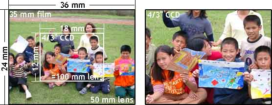
The crop factor is relative to the 35mm film format. If a smaller sensor is used, as in most digicams, the field of view is cropped by the sensor to smaller than the 35mm full-frame format’s field of view. This narrowing of the field of view may be described as crop factor, a factor by which a longer focal length lens would be needed to get the same field of view on a 35mm film camera. Full-frame digital SLRs utilize a sensor of the same size as a frame of 35mm film.

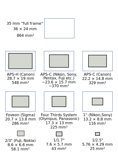
Common values for field of view crop in DSLRs using active pixel sensors include 1.3x for some Canon (APS-H) sensors, 1.5x for Sony APS-C sensors used by Nikon, Pentax and Konica Minolta and for Fujifilm sensors, 1.6 (APS-C) for most Canon sensors, ~1.7x for Sigma‘s Foveon sensors and 2x for Kodak and Panasonic 4/3-inch sensors currently used by Olympus and Panasonic. Crop factors for non-SLR consumer compact and bridge cameras are larger, frequently 4x or more.

Further information: Image sensor format
Table of sensor sizes[9]
Type Width (mm) Height (mm) Size (mm²)
1/3.6″ 4.00 3.00 12.0
1/3.2″ 4.54 3.42 15.5
1/3″ 4.80 3.60 17.3
1/2.7″ 5.37 4.04 21.7
1/2.5″ 5.76 4.29 24.7
1/2.3″ 6.16 4.62 28.5
1/2″ 6.40 4.80 30.7
1/1.8″ 7.18 5.32 38.2
1/1.7″ 7.60 5.70 43.3
2/3″ 8.80 6.60 58.1
1″ 12.8 9.6 123
4/3″ 18.0 13.5 243
APS-C 25.1 16.7 419
35 mm 36 24 864
Back 48 36 1728

lenscropfactor

Field-of-view crop in cameras of different sensor size but the same lens focal length.


kids_50mm_100mm

sensorsizes-svg

Relative sizes of sensors used in most current digital cameras.


以及攝影中所謂 35 mm 等效焦距之說法︰

35 mm equivalent focal length

In photography, the 35 mm equivalent focal length is a measure that indicates the angle of view of a particular combination of a camera lens and film or sensor size. The term is useful because most photographers experienced with interchangeable lenses are most familiar with the 35 mm film format.

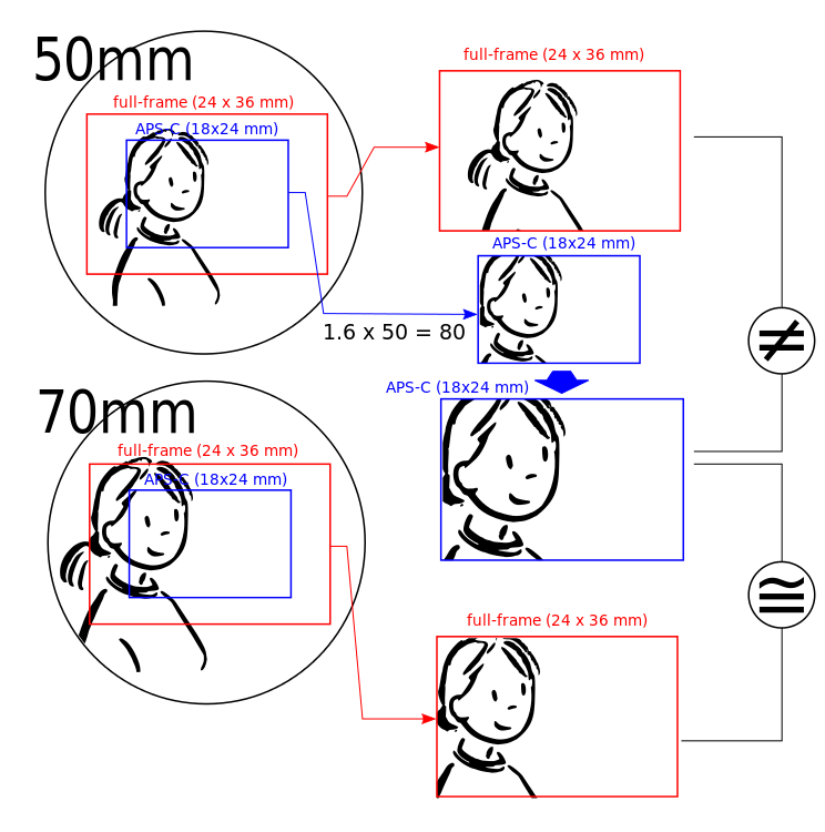
On any 35 mm film camera, a 28 mm lens is a wide-angle lens, and a 200 mm lens is a long-focus lens. However, now that digital cameras have mostly replaced 35 mm cameras, there is no uniform relation between the focal length of a lens and the angle of view, since the size of the camera sensor also determines angle of view, and sensor size is not standardized as film size was. The 35 mm equivalent focal length of a particular lens–sensor combination is the focal length that one would need for a 35 mm film camera to obtain the same angle of view.

Most commonly, the 35 mm equivalent focal length is based on equal diagonal angle of view.[1] This definition also in the CIPA guideline DCG-001.[2] Alternatively, it may sometimes be based on horizontal angle of view. Since 35 mm film is normally used for images with an aspect ratio (width-to-height ratio) of 3:2, while many digital cameras have a 4:3 aspect ratio, which have different diagonal-to-width ratios, these two definitions are often not equivalent.

744px-full-frame_vs_aps-c-svg

The resulting images from 50 mm and 70 mm lenses for different sensor sizes; 36×24 mm (red) and 24×18 mm (blue)


閱讀鏡頭規格時,務須留心也!