由於過去曾寫《專題》,詳細介紹了純數據程式以及環境的點點滴滴 ,這裡就不再贅述,還請讀者自行參照閱讀吧。
比方說,既有了 adc~ 麥克風物件,自可用延遲線 delay line 製造回聲效果︰
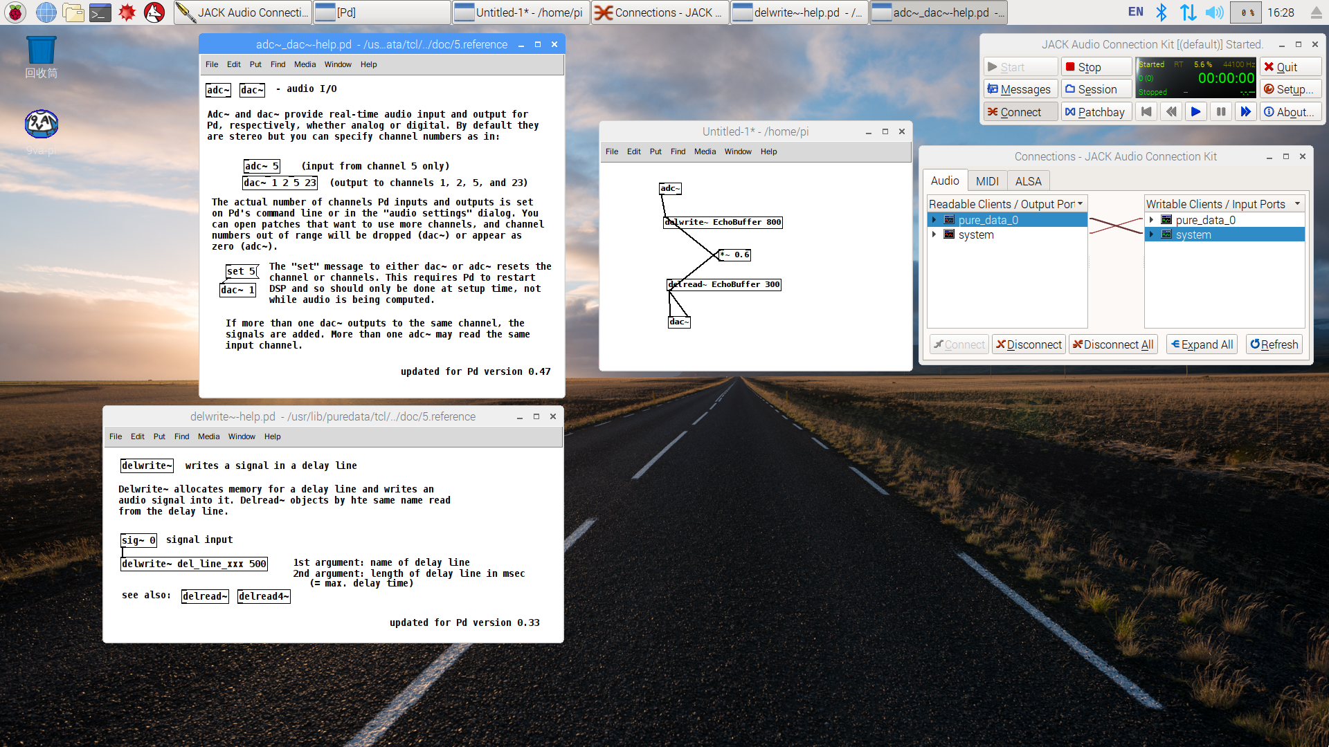
或可重現往日情懷哩!
Echoplex
The Echoplex is a tape delay effect, first made in 1959. Designed by Mike Battle,[1] the Echoplex set a standard for the effect in the 1960s—it is still regarded as “the standard by which everything else is measured.”[2] It was used by some of the most notable guitar players of the era; original Echoplexes are highly sought after.
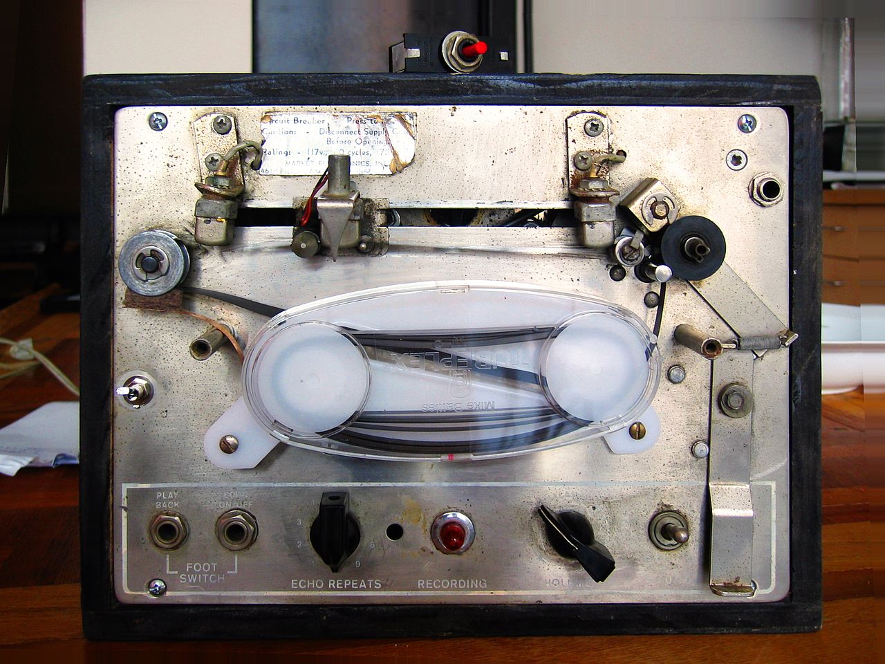
Echoplex EP-2
The original tube Echoplex
Tape echoes work by recording sound on a magnetic tape, which is then played back; the tape speed or distance between heads determine the delay, while a feedback variable (where the delayed sound is delayed again) allows for a repetitive effect.[3] The predecessor of the Echoplex was a tape echo designed by Ray Butts in the 1950s, who built it into a guitar amplifier called the EchoSonic. He built fewer than seventy of them and could never keep up with the demand; they were used by players like Chet Atkins, Scotty Moore, and Carl Perkins.[4] Electronics technician Mike Battle copied the design and built it into a portable unit;[5] another version, however, states that Battle, working with a guitar player named Don Dixon from Akron, Ohio, perfected Dixon’s original creation.[2]
The first Echoplex with vacuum tubes was marketed in 1961. Their big innovation was the moving head, which allowed the operator to change the delay time. In 1962, their patent was bought by a company called Market Electronics in Cleveland, Ohio. Market Electronics built the units and kept designers Battle and Dixon as consultants; they marketed the units through distributor Maestro, hence the name, Maestro Echoplex. In the 1950s, Maestro was a leader in vacuum tube technology. It had close ties with Gibson, and often manufactured amplifiers for Gibson. Later, Harris-Teller of Chicago took over production.[2] The first tube Echoplex had no number designation, but was retroactively designated the EP-1 after the unit received its first upgrade. The upgraded unit was designated the EP-2.[1] These two units set the standard for the delay effect, with their “warm, round, thick echo.”[6] Two of Battle’s improvements over earlier designs were key — the adjustable tape head, which allowed for variable delay, and a cartridge containing the tape, protecting it to retain sound quality.[2]
The Echoplex wasn’t notable just for the delay, but also for the sound; it is “still a classic today, and highly desirable for a range of playing styles … warm, rich, and full-bodied.”[7] The delay could be turned off and the unit used as a filter, thanks to the sound of the vacuum tubes; this is how Tom Verlaine uses it, for instance.
While Echoplexes were used mainly by guitar players (and the occasional bass player, such as Chuck Rainey,[8] or trumpeter, such as Don Ellis[9] or Miles Davis[10][11]), many recording studios also used the Echoplex.[12]
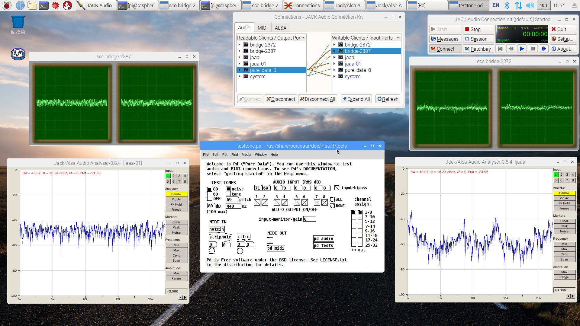
若講借著 PureData 度量 Micphone 頻率響應︰
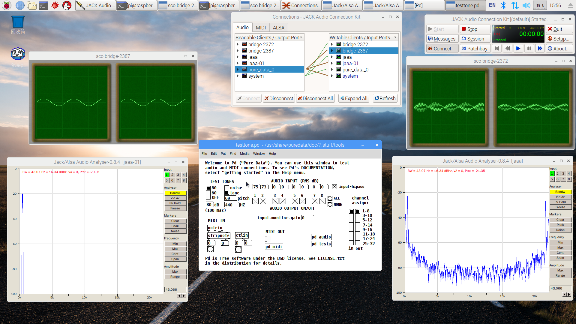
即使大白天,沒有隔音室,怕耳朵受不了也!!
故而作者偏好利用白雜訊?
White noise
In signal processing, white noise is a random signal having equal intensity at different frequencies, giving it a constant power spectral density.[1] The term is used, with this or similar meanings, in many scientific and technical disciplines, including physics, acoustic engineering, telecommunications, statistical forecasting, and many more. White noise refers to a statistical model for signals and signal sources, rather than to any specific signal.
In discrete time, white noise is a discrete signal whose samples are regarded as a sequence of serially uncorrelated random variables with zero mean and finite variance; a single realization of white noise is a random shock. Depending on the context, one may also require that the samples be independent and have identical probability distribution (in other words i.i.d. is the simplest representative of the white noise).[2] In particular, if each sample has a normal distribution with zero mean, the signal is said to be Gaussian white noise.[3]
The samples of a white noise signal may be sequential in time, or arranged along one or more spatial dimensions. In digital image processing, the pixels of a white noise image are typically arranged in a rectangular grid, and are assumed to be independent random variables with uniform probability distribution over some interval. The concept can be defined also for signals spread over more complicated domains, such as a sphere or a torus.
An infinite-bandwidth white noise signal is a purely theoretical construction. The bandwidth of white noise is limited in practice by the mechanism of noise generation, by the transmission medium and by finite observation capabilities. Thus, random signals are considered “white noise” if they are observed to have a flat spectrum over the range of frequencies that are relevant to the context. For an audio signal, for example, the relevant range is the band of audible sound frequencies, between 20 and 20,000 Hz. Such a signal is heard as a hissing sound, resembling the /sh/ sound in “ash”. In music and acoustics, the term “white noise” may be used for any signal that has a similar hissing sound.
White noise draws its name from white light,[4] although light that appears white generally does not have a flat spectral power density over the visible band.
The term white noise is sometimes used in the context of phylogenetically based statistical methods to refer to a lack of phylogenetic pattern in comparative data.[5] It is sometimes used in non technical contexts, in the metaphoric sense of “random talk without meaningful contents”.[6][7]
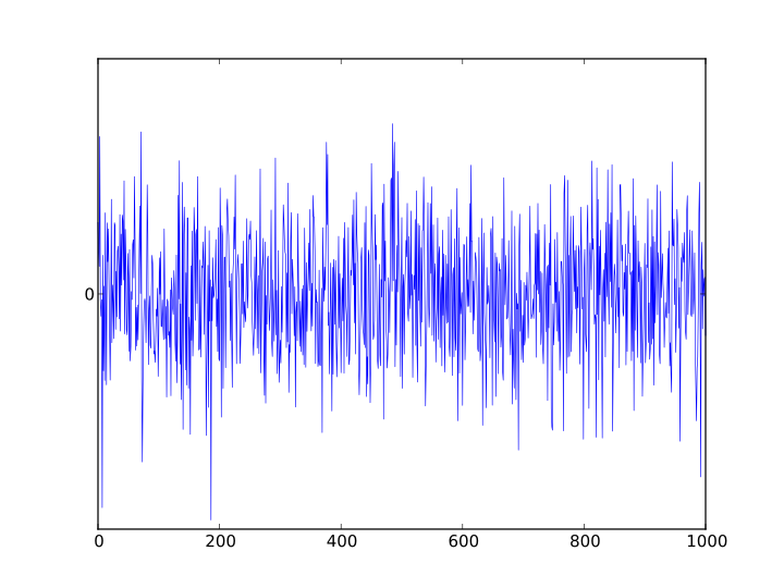
Plot of a Gaussian white noise signal
……
Practical applications
Music
White noise is commonly used in the production of electronic music, usually either directly or as an input for a filter to create other types of noise signal. It is used extensively in audio synthesis, typically to recreate percussive instruments such as cymbals or snare drums which have high noise content in their frequency domain.
Electronics engineering
White noise is also used to obtain the impulse response of an electrical circuit, in particular of amplifiers and other audio equipment. It is not used for testing loudspeakers as its spectrum contains too great an amount of high frequency content. Pink noise, which differs from white noise in that it has equal energy in each octave, is used for testing transducers such as loudspeakers and microphones.
Acoustics
To set up the equalization for a concert or other performance in a venue, a short burst of white or pink noise is sent through the PA system and monitored from various points in the venue so that the engineer can tell if the acoustics of the building naturally boost or cut any frequencies. The engineer can then adjust the overall equalization to ensure a balanced mix.
Computing
White noise is used as the basis of some random number generators. For example, Random.org uses a system of atmospheric antennae to generate random digit patterns from white noise.
………
估量麥克風效能呦??
實亦有所本矣◎
Sound System Measurements using Time Delay Spectrometry
This web site is part of a project done for Dr. Baraniuk’s ELEC 301 class (Fall 2000) at Rice University.
The Problem | How TDS Works | Applications | Other Measurement Techniques | Future Projects
What is TDS?
TDS, or Time Delay Spectrometry, is a technique that can be used to measure the system response of electro-acoustical systems (such as a loudspeakers) in “real-world” reverberant environments. The technique can also be expanded to measure the system response of an acoustic environment such as an auditorium or concert hall. TDS lends itself naturally to obtaining three dimensional TEF (time-energy-frequency) plots of system response. Although the mathematical and conceptual basis behind TDS have been known for quite some time, the TDS technique itself is usually credited to the late Dr. Richard Heyser, who first published the technique in the 1967 Journal of the Audio Engineering Society.
…
The Problem
How do we measure the system response of a loudspeaker in a reverberant environment?
If we assume that the system under test is LTI, we can completely describe the system using either one of the two system responses, since they are related by the Fourier transform. The impulse response implies the frequency response and vice versa–each one is saying the same thing, just in a different way.
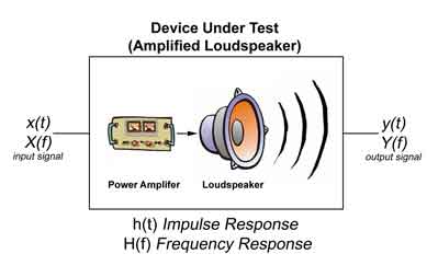
Trying to measure the system response of a loudspeaker system in a “real-world” environment can often be quite challenging. Given the finite voltage handling limits of a real-world speaker system, any attempt to apply an impulse function at the input terminals would cause the system to turn into a chunk of smoldering carbon, or at the very least, cause our system to become nonlinear.
Getting a frequency response, on the other hand, seems relatively simple. We could just feed in an electrical input signal X(f), note the mechanical (pressure) signal, Y(f), coming out of the system, and then divide the frequency output by the frequency input to get our transfer function H(f)=Y(f)/X(f).
In a real-world environment, however, using the technique described above would lead to a flawed transfer function.
Why?
Sound is a compression wave in air, and most rooms are comprised of surfaces (walls, floors, ceilings, not to mention furniture like desks and chairs), that cause acoustical scattering of the wavefront emitted by the speaker. Surfaces inside the room tend to reflect, transmit, and absorb sound to varying degrees. How a surface acts varies greatly depending upon its composition, but hard surfaces like tile tend to reflect sound, although some materials, like metal, can act as ‘conductors’ or ‘transmitters’ of sound. Softer surfaces, on the other hand, like carpet and foam, tend to absorb or ‘damp’ sound.
One solution to this problem is to create an environment that allows for no acoustical scattering. Such ‘dead rooms’, also called anechoic chambers, are usually very expensive to build and maintain.
What we need is a method to measure the response of such as system regardless of the acoustic environment in which the system is located.
One solution, usually credited to the late Dr. Richard Heyser, is called Time Delay Spectrometry. The technique was first published in the Journal of the Audio Engineering Society in October 1967.
……
Other Measurement Techniques
Since we are trying to find an impulse response, what we are really doing is using our test signal (swept sine wave for TDS) to model an ideal impulse function. As we increase the amount of energy per unit time contained in our test signal, our measurement becomes more and more like the ‘real’ impulse response. We must have as much energy in our signal as possible in order to maintain a high signal-to-noise ratio for our measurement. This is especially important in an environment where ambient noise levels are high (in real-world venues, we must consider HVAC, industrial sounds, and possibly even things like audience noise).
One convenient measure of how much energy our signal contains per unit time is the crest factor. The crest factor of a signal is simply the ratio of peak value of the signal and the RMS value of the signal:
crest factor = (peak value) / (RMS value).
Ideally, we would like our crest factor to be as close to 1 as possible. Since our peak value and RMS value would be the same, we cannot have any more energy per unit time in our signal, and our input signal can be said more closely resemble an idealized impulse.
Our swept sine wave input has a crest factor of sqrt(2), which is approximately 1.4.
Another kind of input signal, which has gained a great deal of popularity in the last few years, is called an MLS, or Maximum Length Sequence. An MLS signal is simply a series of pseudo-random pulses generated by an MLS random number generator. Usually, these pulses are white or pink noise signals (pink noise is like random white noise, but it has equal power for each octave in the frequency domain).
The crest factor for MLS is very close to 1, so it makes sense to use this kind of input signal when we need a high signal-to-noise ratio for our measurement. MLS works well for the noisy real-world environments that are ever so prevalent in acoustics testing.
………