差不多先生傳‧胡適
你知道中國最有名的人是誰?提起此人,人人皆曉,處處聞名,他姓差,名不多,是各省各縣各村人氏。你一定見過他,一定聽過別人談起他,差不多先生的名字,天天掛在大家的口頭,因為他是中國全國人的代表。
差不多先生的相貌,和你和我都差不多。他有一雙眼睛,但看的不很清楚;有兩隻耳朵,但聽的不很分明;有鼻子和嘴,但他對於氣味和口味都不很講究;他的腦子也不小,但他的記性卻不很精明,他的思想也不細密。
他常常說:「凡事只要差不多,就好了。何必太精明呢?」
他小時候,他媽叫他去買紅糖,他買了白糖回來,他媽罵他,他搖搖頭道:「紅糖,白糖,不是差不多嗎?」
他在學堂的時候,先生問他:「直隸省的西邊是哪一省?」他說是陝西。先生說:「錯了,是山西,不是陝西。」他說:「陝西同山西,不是差不多嗎?」
後來他在一個錢鋪裏做夥計;他也會寫,也會算,只是總不會精細 ;十字常常寫成千字,千字常常寫成十字。掌櫃的生氣了,常常罵他,他只笑嘻嘻地賠小心道:「千字比十字多一小撇,不是差不多嗎?」
有 一天,他為了一件要緊的事,要搭火車到上海去,他從從容容地走到火車站,遲了兩分鐘,火車已開走了。他白瞪著眼,望著遠遠的火車上的煤煙,搖搖頭道:「只 好明天再走了,今天走同明天走 ,也還差不多;可是火車公司未免太認真了。八點三十分開,同八點三十二分開,不是差不多嗎?」他一面說,一面慢慢地走回家,心裏總不很明白為甚麼火車不肯 等他兩分鐘。
有 一天,他忽然得一急病,趕快叫家人去請東街的汪先生。那家人急急忙忙跑去,一時尋不著東街的汪大夫,卻把西街的牛醫王大夫請來了。差不多先生病在脇上,知 道尋錯了人;但病急了,身上痛苦,心裏焦急,等不得了,心裏想道:「好在王大夫同汪大夫也差不多,讓他試試看罷。」於是這位牛醫王大夫走近脇前,用醫牛的 法子給差不多先生治病。不上一點鐘,差不多先生就一命嗚呼了。
差不多先生差不多要死的時候,一口氣斷斷續續地說道:「活人同死人也差……差……差……不多,……凡事只要……差……差……不多……就……好了,何……必……太……太認真呢?」他說完了這句格言,就絕了氣。
他死後,大家都很稱讚差不多先生樣樣事情看得破,想得通;大家都說他一生不肯認真,不肯算帳,不肯計較,真是一位有德行的人 。於是大家給他取個死後的法號,叫他做圓通大師。
他的名譽愈傳愈遠,愈久愈大,無數無數的人,都學他的榜樣,於是人人都成了一個差不多先生。──然而中國從此就成了一個懶人國了。
試想『相機』所見與『隻眼』相同嗎?之前《光的世界》系列文本已嚐試解說過很多『光學系統』問題哩!
若問看似簡單的『針孔相機模型』
The pinhole camera model describes the mathematical relationship between the coordinates of a 3D point and its projection onto the image plane of an ideal pinhole camera, where the camera aperture is described as a point and no lenses are used to focus light. The model does not include, for example, geometric distortions or blurring of unfocused objects caused by lenses and finite sized apertures. It also does not take into account that most practical cameras have only discrete image coordinates. This means that the pinhole camera model can only be used as a first order approximation of the mapping from a 3D scene to a 2D image. Its validity depends on the quality of the camera and, in general, decreases from the center of the image to the edges as lens distortion effects increase.
Some of the effects that the pinhole camera model does not take into account can be compensated, for example by applying suitable coordinate transformations on the image coordinates, and other effects are sufficiently small to be neglected if a high quality camera is used. This means that the pinhole camera model often can be used as a reasonable description of how a camera depicts a 3D scene, for example in computer vision and computer graphics.
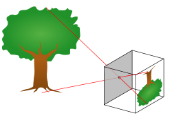
A diagram of a pinhole camera.
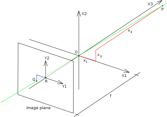
The geometry and mathematics of the pinhole camera
NOTE: The x1x2x3 coordinate system in the figure is left-handed, that is the direction of the OZ axis is in reverse to the system the reader may be used to.
The geometry related to the mapping of a pinhole camera is illustrated in the figure. The figure contains the following basic objects:
- A 3D orthogonal coordinate system with its origin at O. This is also where the camera aperture is located. The three axes of the coordinate system are referred to as X1, X2, X3. Axis X3 is pointing in the viewing direction of the camera and is referred to as the optical axis, principal axis, or principal ray. The 3D plane which intersects with axes X1 and X2 is the front side of the camera, or principal plane.
- An image plane where the 3D world is projected through the aperture of the camera. The image plane is parallel to axes X1 and X2 and is located at distance
 from the origin O in the negative direction of the X3 axis. A practical implementation of a pinhole camera implies that the image plane is located such that it intersects the X3 axis at coordinate -f where f > 0. f is also referred to as the focal length[citation needed] of the pinhole camera.
- A point R at the intersection of the optical axis and the image plane. This point is referred to as the principal point or image center.
- A point P somewhere in the world at coordinate
 relative to the axes X1,X2,X3.
- The projection line of point P into the camera. This is the green line which passes through point P and the point O.
- The projection of point P onto the image plane, denoted Q. This point is given by the intersection of the projection line (green) and the image plane. In any practical situation we can assume that
 > 0 which means that the intersection point is well defined.
- There is also a 2D coordinate system in the image plane, with origin at R and with axes Y1 and Y2 which are parallel to X1 and X2, respectively. The coordinates of point Q relative to this coordinate system is
 .
.
The geometry of a pinhole camera
The pinhole aperture of the camera, through which all projection lines must pass, is assumed to be infinitely small, a point. In the literature this point in 3D space is referred to as the optical (or lens or camera) center.[1]
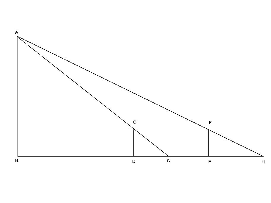
Next we want to understand how the coordinates of point Q depend on the coordinates of point P. This can be done with the help of the following figure which shows the same scene as the previous figure but now from above, looking down in the negative direction of the X2 axis.

The geometry of a pinhole camera as seen from the X2 axis
In this figure we see two similar triangles, both having parts of the projection line (green) as their hypotenuses. The catheti of the left triangle are  and f and the catheti of the right triangle are
  and . Since the two triangles are similar it follows that
 or
or 
A similar investigation, looking in the negative direction of the X1 axis gives
 or
or 
This can be summarized as
-

which is an expression that describes the relation between the 3D coordinates of point P and its image coordinates given by point Q in the image plane.
─── 摘自《光的世界︰矩陣光學二》
,為什麼沒有介紹其實際矩陣運算的呢??
因為那時就勢必得進入
投影平面
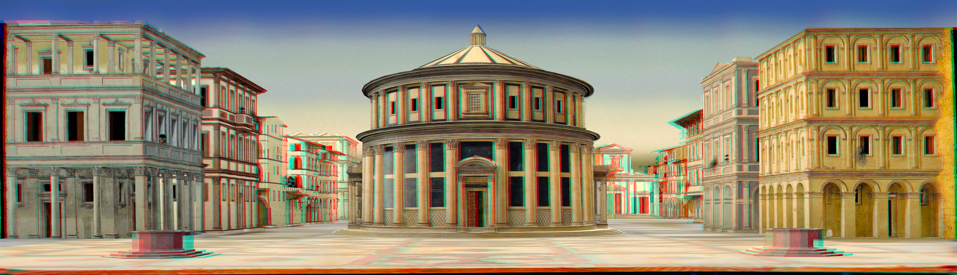
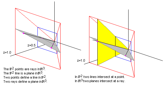
在數學裡,投影平面(projective plane)是一個延伸平面概念的幾何結構。在普通的歐氏平面裡,兩條線通常會相交於一點,但有些線(即平行線)不會相交。投影平面可被認為是個具有額外的「無窮遠點」之一般平面,平行線會於該點相交。因此,在投影平面上的兩條線會相交於一個且僅一個點。
文藝復興時期的藝術家在發展透視投影的技術中,為此一數學課題奠定了基礎。投影平面的典型範例為實投影平面,亦稱為「擴展歐氏平面」。此一範例在代數幾何、拓撲學及投影幾何內都很重要,在各領域內的形式均略有不同,可標計為 PG(2, R)、RP2 或 P2(R) 等符號。還有許多其他的投影平面,包括無限(如複投影平面)與有限(如法諾平面)之類型。
投影平面是二維投影空間,但並不是所有投影平面都可以嵌入三維投影空間內。投影平面是否能嵌入三維投影空間取決於該平面是否為笛沙格平面。
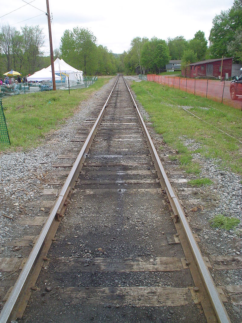
兩條平行線似乎相交於「無窮遠處」的消失點。在投影平面裡,這是真的。
※ 註
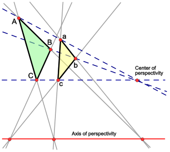
笛沙格(Desargues)定理說明:在射影空間中,有六點A,B,C,a,b,c。Aa,Bb,Cc共點若且唯若AB∩ab,BC∩bc,CA∩ca共線。
在射影幾何的對偶性來看,笛沙格定理是自對偶的。
也!!
要如何簡易講此『實射影平面』乎??
In mathematics, the real projective plane is an example of a compact non-orientable two-dimensional manifold; in other words, a one-sided surface. It cannot be embedded in standard three-dimensional space without intersecting itself. It has basic applications to geometry, since the common construction of the real projective plane is as the space of lines in R3 passing through the origin.
The plane is also often described topologically, in terms of a construction based on the Möbius strip: if one could glue the (single) edge of the Möbius strip to itself in the correct direction, one would obtain the projective plane. (This cannot be done in three-dimensional space.) Equivalently, gluing a disk along the boundary of the Möbius strip gives the projective plane. Topologically, it has Euler characteristic 1, hence a demigenus (non-orientable genus, Euler genus) of 1.
Since the Möbius strip, in turn, can be constructed from a square by gluing two of its sides together, the real projective plane can thus be represented as a unit square (that is, [0,1] × [0,1] ) with its sides identified by the following equivalence relations:
- (0, y) ~ (1, 1 − y) for 0 ≤ y ≤ 1
and
- (x, 0) ~ (1 − x, 1) for 0 ≤ x ≤ 1,
as in the leftmost diagram on the right.

The fundamental polygon of the projective plane. |

The Möbius strip with a single edge, can be closed into a projective plane by gluing opposite open edges together. |

In comparison the Klein bottle is a Möbius strip closed into a cylinder. |
將怎樣闡釋必須用『齊次座標系』耶
Homogeneous coordinates
The points in the plane can be represented by homogeneous coordinates. A point has homogeneous coordinates [x : y : z], where the coordinates [x : y : z] and [tx : ty : tz] are considered to represent the same point, for all nonzero values of t. The points with coordinates [x : y : 1] are the usual real plane, called the finite part of the projective plane, and points with coordinates [x : y : 0], called points at infinity or ideal points, constitute a line called the line at infinity. (The homogeneous coordinates [0 : 0 : 0] do not represent any point.)
The lines in the plane can also be represented by homogeneous coordinates. A projective line corresponding to the plane ax + by + cz = 0 in R3 has the homogeneous coordinates (a : b : c). Thus, these coordinates have the equivalence relation (a : b : c) = (da : db : dc) for all nonzero values of d. Hence a different equation of the same line dax + dby + dcz = 0 gives the same homogeneous coordinates. A point [x : y : z] lies on a line (a : b : c) if ax + by + cz = 0. Therefore, lines with coordinates (a : b : c) where a, b are not both 0 correspond to the lines in the usual real plane, because they contain points that are not at infinity. The line with coordinates (0 : 0 : 1) is the line at infinity, since the only points on it are those with z = 0.
Points, lines, and planes
A line in P2 can be represented by the equation ax + by + cz = 0. If we treat a, b, and c as the column vector ℓ and x, y, z as the column vector x then the equation above can be written in matrix form as:
- xTℓ = 0 or ℓTx = 0.
Using vector notation we may instead write
- x ⋅ ℓ = 0 or ℓ ⋅ x = 0.
The equation k(xTℓ) = 0 (which k is a non-zero scalar) sweeps out a plane that goes through zero in R3 and k(x) sweeps out a line, again going through zero. The plane and line are linear subspaces in R3, which always go through zero.
Ideal points
In P2 the equation of a line is ax + by + c = 0 and this equation can represent a line on any plane parallel to the x, y plane by multiplying the equation by k.
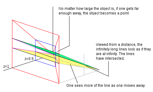
If z = 1 we have a normalized homogeneous coordinate. All points that have z = 1 create a plane. Let’s pretend we are looking at that plane (from a position further out along the z axis and looking back towards the origin) and there are two parallel lines drawn on the plane. From where we are standing (given our visual capabilities) we can see only so much of the plane, which we represent as the area outlined in red in the diagram. If we walk away from the plane along the z axis, (still looking backwards towards the origin), we can see more of the plane. In our field of view original points have moved. We can reflect this movement by dividing the homogeneous coordinate by a constant. In the adjacent image we have divided by 2 so the z value now becomes 0.5. If we walk far enough away what we are looking at becomes a point in the distance. As we walk away we see more and more of the parallel lines. The lines will meet at a line at infinity (a line that goes through zero on the plane at z = 0). Lines on the plane when z = 0 are ideal points. The plane at z = 0 is the line at infinity.
The homogeneous point (0, 0, 0) is where all the real points go when you’re looking at the plane from an infinite distance, a line on the z = 0 plane is where parallel lines intersect.
Duality
In the equation xTℓ = 0 there are two column vectors. You can keep either constant and vary the other. If we keep the point x constant and vary the coefficients ℓ we create new lines that go through the point. If we keep the coefficients constant and vary the points that satisfy the equation we create a line. We look upon x as a point, because the axes we are using are x, y, and z. If we instead plotted the coefficients using axis marked a, b, c points would become lines and lines would become points. If you prove something with the data plotted on axis marked x, y, and z the same argument can be used for the data plotted on axis marked a, b, and c. That is duality.

Lines joining points and intersection of lines (using duality)
The equation xTℓ = 0 calculates the inner product of two column vectors. The inner product of two vectors is zero if the vectors are orthogonal. In P2, the line between the points x1 and x2 may be represented as a column vector ℓ that satisfies the equations x1Tℓ = 0 and x2Tℓ = 0, or in other words a column vector ℓ that is orthogonal to x1 and x2. The cross product will find such a vector: the line joining two points has homogeneous coordinates given by the equation x1 × x2. The intersection of two lines may be found in the same way, using duality, as the cross product of the vectors representing the lines, ℓ1 × ℓ2.
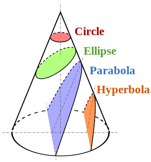
更別想當初也曾困惑『圓錐曲線』呀◎


 』的一般?!已經完全不像他的『白馬非馬論』了。


 ,故而很難『度量』的『精準』,一點點『角度』之『誤差』就產生了那個
 之物,若位在『無窮遠』
  處,竟然它的『視角』 能不趨近於『零』
  嗎??
嗎??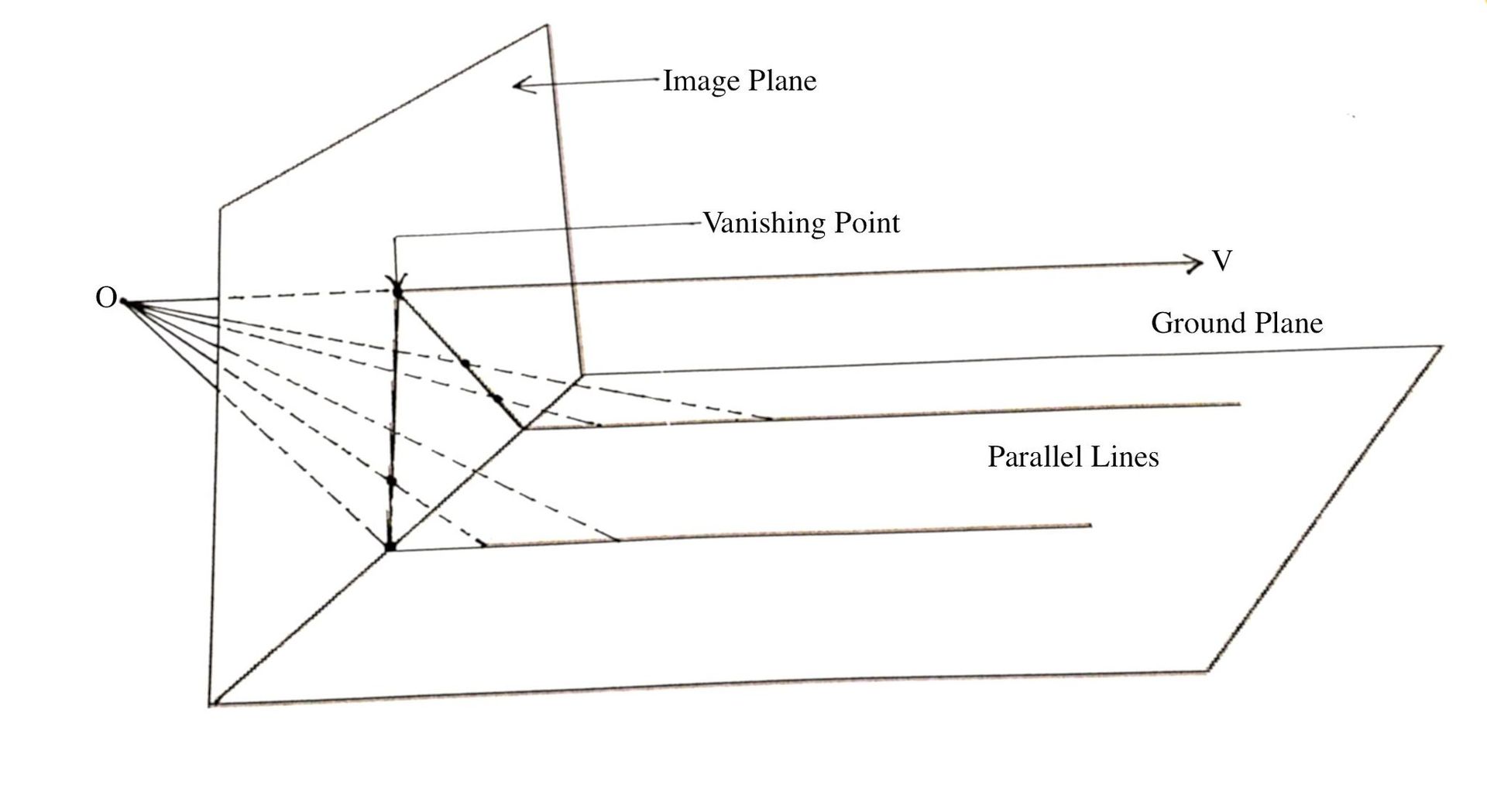


 必真。
必真。 ,將平面分成『三』個區域,『