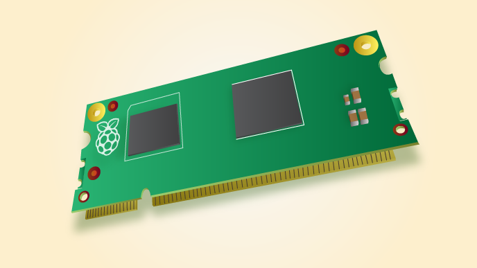
雖說樹莓派 HATs 並非大部頭之規格︰
B+ HAT requirements
A board can only be called a HAT if:
- It conforms to the basic add-on board requirements
- It has a valid ID EEPROM (including vendor info, GPIO map and valid device tree information).
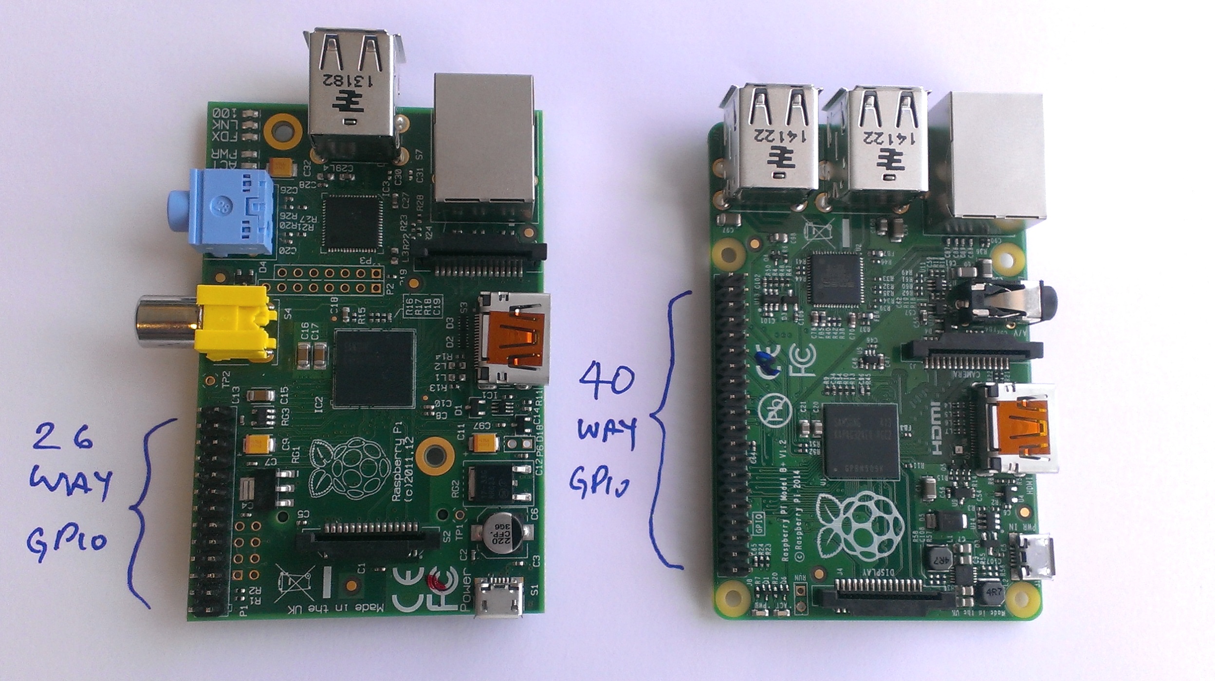
- It has a full size 40W GPIO connector.
- It follows the HAT mechanical specification
- It uses a GPIO connector that spaces the HAT between 10mm and 12mm from the Pi (i.e. uses spacers between 10mm and 12mm).
- If back powering via the GPIO connector the HAT must be able to supply a minimum of 1.3A continuously to the Pi (but ability to supply 2A continuously recommended).
Of course users are free to put an ID EEPROM on boards that don’t otherwise conform to the remainder of the specifications – in fact we strongly encourage this; we just want things called HATs to be a known and well-specified entity to make life easier for customers, particularly the less technical ones.
Design Resources
Before designing any new add-on board (HAT compliant or not) please read the design guide carefully.
For what to flash into the ID EEPROM see the ID EEPROM data format spec.
There are tools and documentation on how to flash ID EEPROMs here.
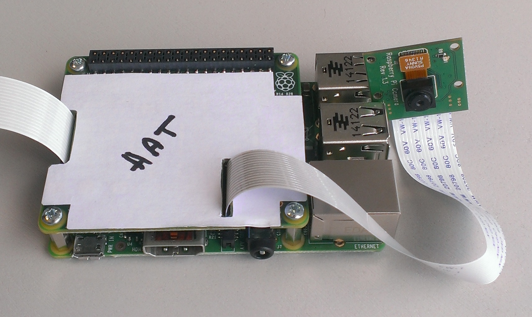
瀏覽過整份文件者,當會發現其實也十分複雜。作者因不知是否有什麼快解速讀之法,通常將之比擬成拼圖,起初略分『已知』、『未知 』的『資料』;初步考察『大架構』、『小部件』的『組成 』。然後隨著『資料』的查詢與收集,架構部件『組成』的理解,一次又一次重新『閱讀』,總能明白的吧!!??由於文本的主要目的是探究 ID EEPROM 與樹莓派軟件系統之關係,因此只以幾張簡單圖示代表一般所謂的 HATs Add-On Card 的了︰
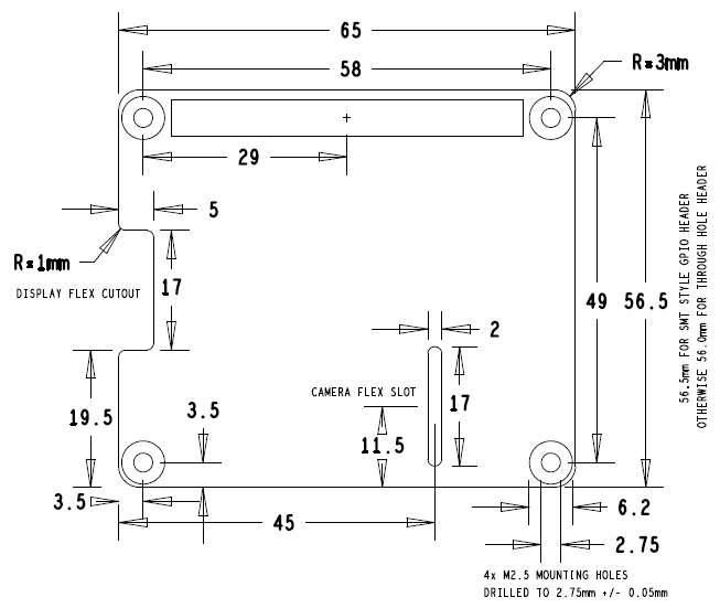
【HATs 機構圖】
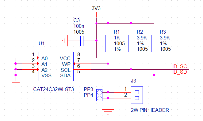
【ID EEPROM 電路圖】
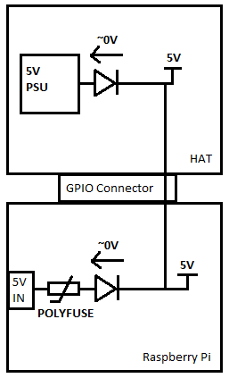
【5V 供電安全性示意圖】
不論用什麼作拼圖之起點,終究選一個理解較多的開始較好,所以作者從命令列之 shell script
#!/bin/sh
MODE="NOT_SET"
FILE="NOT_SET"
TYPE="NOT_SET"
usage()
{
echo "eepflash: Writes or reads .eep binary image to/from HAT EEPROM on a Raspberry Pi"
echo ""
echo "./eepflash.sh"
echo " -h --help: display this help message"
echo " -r --read: read .eep from the eeprom"
echo " -w --write: write .eep to the eeprom"
echo " -f=file_name --file=file_name: binary .eep file to read to/from"
echo " -t=eeprom_type --type=eeprom_type: eeprom type to use"
echo " We support the following eeprom types:"
echo " -24c32"
echo " -24c64"
echo " -24c128"
echo " -24c256"
echo " -24c512"
echo " -24c1024"
echo ""
}
………
modprobe i2c_dev
dtoverlay i2c-gpio i2c_gpio_sda=0 i2c_gpio_scl=1
rc= rc != 0 ]; then
echo "Loading of i2c-gpio dtoverlay failed. Do an rpi-update (and maybe apt-get update; apt-get upgrade)."
exit
rc != 0 ]; then
echo "Loading of i2c-gpio dtoverlay failed. Do an rpi-update (and maybe apt-get update; apt-get upgrade)."
exit  ?
if [
?
if [ ![rc != 0 ]; then echo "Modprobe of at24 failed. Do an rpi-update." exit](http://www.freesandal.org/wp-content/ql-cache/quicklatex.com-effc49e04670b69d9f957a7f1079e8b1_l3.png "Rendered by QuickLaTeX.com") rc
fi
if [ ! -d "/sys/class/i2c-adapter/i2c-3/3-0050" ]; then
echo "
rc
fi
if [ ! -d "/sys/class/i2c-adapter/i2c-3/3-0050" ]; then
echo " MODE" = "write" ]
then
echo "Writing..."
dd if=
MODE" = "write" ]
then
echo "Writing..."
dd if= ?
elif [ "
?
elif [ "![MODE" = "read" ] then echo "Reading..." dd if=/sys/class/i2c-adapter/i2c-3/3-0050/eeprom of=](http://www.freesandal.org/wp-content/ql-cache/quicklatex.com-88b9eaf27754c0e7e6b61332bc966897_l3.png "Rendered by QuickLaTeX.com") FILE
rc=
FILE
rc= rc != 0 ]; then
echo "Error doing I/O operation."
exit
rc != 0 ]; then
echo "Error doing I/O operation."
exit  TYPE 0x50" > /sys/class/i2c-adapter/i2c-3/new_device
的意義︰
Linux/Documentation/i2c/instantiating-devices
TYPE 0x50" > /sys/class/i2c-adapter/i2c-3/new_device
的意義︰
Linux/Documentation/i2c/instantiating-devices
207 Method 4: Instantiate from user-space
208 -------------------------------------
209
210 In general, the kernel should know which I2C devices are connected and
211 what addresses they live at. However, in certain cases, it does not, so a
212 sysfs interface was added to let the user provide the information. This
213 interface is made of 2 attribute files which are created in every I2C bus
214 directory: new_device and delete_device. Both files are write only and you
215 must write the right parameters to them in order to properly instantiate,
216 respectively delete, an I2C device.
217
218 File new_device takes 2 parameters: the name of the I2C device (a string)
219 and the address of the I2C device (a number, typically expressed in
220 hexadecimal starting with 0x, but can also be expressed in decimal.)
221
222 File delete_device takes a single parameter: the address of the I2C
223 device. As no two devices can live at the same address on a given I2C
224 segment, the address is sufficient to uniquely identify the device to be
225 deleted.
226
227 Example:
228 # echo eeprom 0x50 > /sys/bus/i2c/devices/i2c-3/new_device
229
230 While this interface should only be used when in-kernel device declaration
231 can't be done, there is a variety of cases where it can be helpful:
232 * The I2C driver usually detects devices (method 3 above) but the bus
233 segment your device lives on doesn't have the proper class bit set and
234 thus detection doesn't trigger.
235 * The I2C driver usually detects devices, but your device lives at an
236 unexpected address.
237 * The I2C driver usually detects devices, but your device is not detected,
238 either because the detection routine is too strict, or because your
239 device is not officially supported yet but you know it is compatible.
240 * You are developing a driver on a test board, where you soldered the I2C
241 device yourself.
242
243 This interface is a replacement for the force_* module parameters some I2C
244 drivers implement. Being implemented in i2c-core rather than in each
245 device driver individually, it is much more efficient, and also has the
246 advantage that you do not have to reload the driver to change a setting.
247 You can also instantiate the device before the driver is loaded or even
248 available, and you don't need to know what driver the device needs.
於是心中大體有了個譜??!!
【I2C 參考文本】
‧W!o+ 的《小伶鼬工坊演義》︰ 一窺全豹之系統設計《解讀》
‧W!o+ 的《小伶鼬工坊演義》︰ 一窺全豹之系統設計‧探索開始