當讀片段濃縮文本
Armature Controlled DC Motor
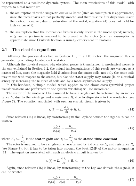
A motor is an actuator, converting electrical energy in to rotational mechanical energy. Motor requiring DC supply for operation is termed as DC motor. DC motors are widely used in control applications like robotics, tape drives, machines and many more. Separately excited DC motors are suitable for control applications because of separate field and armature circuit. Two ways to control DC separately excited motors are:
1. Armature Control.
2. Field Control.
Modelling of armature control DC motor is discussed in the article.
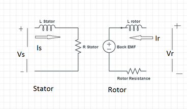
It represents basic structure of separately excited DC motor.
Basic operating mechanism of a DC motor[1]
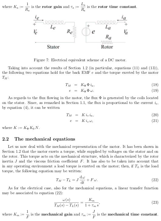
DC motor consists of two parts i.e. rotor and stator. Stator consists of field winding while rotor (also called armature) consists of armature winding. When both armature and field are excited by DC supply, current flows through windings and magnetic flux proportional to the current is produced. When the flux of field interacts with the flux of armature, it results in motion of the rotor. Armature control is the most common control technique for DC motors. In order to implement this control, the flux is required to be kept constant. To this aim, either the stator voltage is constant or the stator coils are replaced by a permanent magnet. In the latter case, the motor is said to be a permanent magnet DC motor and is driven by means of the only armature coils.
As in armature control, field flux is constant; equations governing operation of motor become linear that is
 (1)
(1)
where  is motor torque,
  is flux and
  is armature current. When field flux is constant, equation (1) becomes
 (2)
(2)
where  as is constant.
In addition, the motor has an intrinsic negative feedback structure, hence at the steady state, the speed  is proportional to the reference input
  .
.
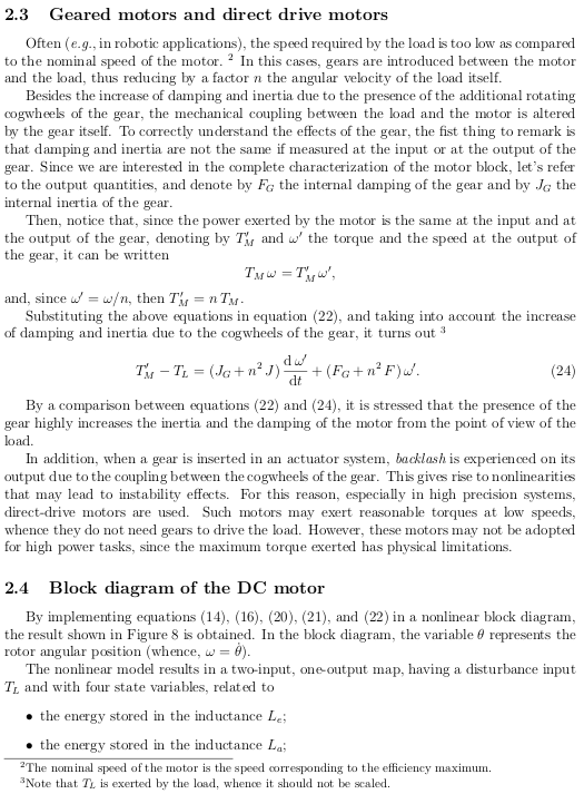
These two facts, in addition to the cheaper price of a permanent magnet motor with respect to a standard DC motor (as a matter of fact only the rotor coils need to be winded), are the main reasons why armature controlled motors are widely used. However, several disadvantages arise from this control technique, of which major is the flow of large currents during transients. For example, when started speed ω is zero initially hence back EMF (Electromotive Force) governed by the following relation, would be zero.
 (3)
(3)
And also armature current is given by  (4)
(4)
will be very high causing increase in heating of machine and it may damage the insulation.
Transfer Function
Essential Equations [1]:
Electrical Equations:
 in Laplace domain (5)
in Laplace domain  (6)
(6)
in Laplace domain  (7)
(7)
 in Laplace domain
  (8)
(8)
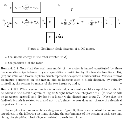
Block Diagram of Separately Excited DC Motor is given in Fig.2
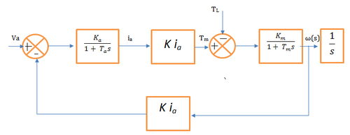
It represents block diagram of separately excited DC motor with armature control.
Various parameters in figure are described as
 is the rotor gain.
 is the electrical time constant.
 is the motor torque.
 is a constant depending on field flux.
 is mechanical gain.
- F is viscous friction coefficient.
 is mechanical time constant, where J is moment of inertia of the load.
 is the resulting angular velocity.
The transfer matrix of the system may be written as
 (9)
(9)
where  (10)
(10)
 (11)
(11)
能不感覺望文生義耶?
此時或不如鉅細靡遺咀嚼大部頭文章也!
DC motors: dynamic model and control techniques
然由『學問』貴在『善用』來講,恐又略嫌不足呦!?
─── 《STEM 隨筆︰古典力學︰轉子【五】《電路學》 五【電感】 IV‧馬達‧二‧D》
試問當已經知道 DC 轉子之『電路模型』,可否用『啟動電流』與『轉動電流』的差異,解釋 PoE HAT 小風扇可能引發之『現象』嗎 ?
若將 PoE HAT 看成

『不理想』電壓源,打算怎麼『改善』呢??
Re: PoE HAT – USB Ports not working – over-current
martinrowan wrote: ↑
Tue Sep 04, 2018 9:43 amIs it the physical distance that makes the difference, for example with long leads/wires attached if you move it close to the RPi does it start to fail. Or is it the length/resistance of the cables that are making a difference?
Good question. I am not 100% sure. I think it is the distance.
In the next step i try to add the capacitors.
As told before: Have a look at the datasheet of the MP8007 chip. Specially the capacitor and the part with the red “X”.
- Attachments
-
- Schematic.JPG (156.7 KiB) Viewed 503 times
……
Re: PoE HAT – USB Ports not working – over-current
Now i can pull 1A from the USB.
It has still some noise, but it looks much better than before.
Now testing how stable it is, if the fan works and so on.
- Attachments
-
- Noise.JPG (133.93 KiB) Viewed 1169 times
-
- Fix.JPG (153.39 KiB) Viewed 1170 times
※ 註︰
───
DC-to-DC converter
A DC-to-DC converter is an electronic circuit or electromechanical device that converts a source of direct current (DC) from one voltage level to another. It is a type of electric power converter. Power levels range from very low (small batteries) to very high (high-voltage power transmission).
……
Terminology
- Step-down
- A converter where output voltage is lower than the input voltage (such as a buck converter).
- Step-up
- A converter that outputs a voltage higher than the input voltage (such as a boost converter).
- Continuous current mode
- Current and thus the magnetic field in the inductive energy storage never reach zero.
- Discontinuous current mode
- Current and thus the magnetic field in the inductive energy storage may reach or cross zero.
- Noise
- Unwanted electrical and electromagnetic signal noise, typically switching artifacts.
- RF noise
- Switching converters inherently emit radio waves at the switching frequency and its harmonics. Switching converters that produce triangular switching current, such as the Split-Pi, forward converter, or Ćuk converter in continuous current mode, produce less harmonic noise than other switching converters.[17] RF noise causes electromagnetic interference (EMI). Acceptable levels depend upon requirements, e.g. proximity to RF circuitry needs more suppression than simply meeting regulations.
- Input noise
- The input voltage may have non-negligible noise. Additionally, if the converter loads the input with sharp load edges, the converter can emit RF noise from the supplying power lines. This should be prevented with proper filtering in the input stage of the converter.
- Output noise
- The output of an ideal DC-to-DC converter is a flat, constant output voltage. However, real converters produce a DC output upon which is superimposed some level of electrical noise. Switching converters produce switching noise at the switching frequency and its harmonics. Additionally, all electronic circuits have some thermal noise. Some sensitive radio-frequency and analog circuits require a power supply with so little noise that it can only be provided by a linear regulator.[citation needed] Some analog circuits which require a power supply with relatively low noise can tolerate some of the less-noisy switching converters, e.g. using continuous triangular waveforms rather than square waves.[17][not in citation given]
───
Switched-mode power supply
A switched-mode power supply (switching-mode power supply, switch-mode power supply, switched power supply, SMPS, or switcher) is an electronic power supply that incorporates a switching regulator toconvert electrical power efficiently. Like other power supplies, an SMPS transfers power from a DC or AC source (often mains power) to DC loads, such as a personal computer, while converting voltage and currentcharacteristics. Unlike a linear power supply, the pass transistor of a switching-mode supply continually switches between low-dissipation, full-on and full-off states, and spends very little time in the high dissipation transitions, which minimizes wasted energy. Ideally, a switched-mode power supply dissipates no power. Voltage regulation is achieved by varying the ratio of on-to-off time. In contrast, a linear power supply regulates the output voltage by continually dissipating power in the pass transistor. This higher power conversion efficiency is an important advantage of a switched-mode power supply. Switched-mode power supplies may also be substantially smaller and lighter than a linear supply due to the smaller transformer size and weight.
Switching regulators are used as replacements for linear regulators when higher efficiency, smaller size or lighter weight are required. They are, however, more complicated; their switching currents can cause electrical noise problems if not carefully suppressed, and simple designs may have a poor power factor.
……
Advantages and disadvantages
The main advantage of the switching power supply is greater efficiency than linear regulators because the switching transistor dissipates little power when acting as a switch.
Other advantages include smaller size and lighter weight from the elimination of heavy line-frequency transformers, and comparable heat generation. Standby power loss is often much less than transformers.
Disadvantages include greater complexity, the generation of high-amplitude, high-frequency energy that the low-pass filter must block to avoid electromagnetic interference (EMI), a ripple voltage at the switching frequency and the harmonic frequencies thereof.
Very low cost SMPSs may couple electrical switching noise back onto the mains power line, causing interference with A/V equipment connected to the same phase. Non-power-factor-corrected SMPSs also cause harmonic distortion.
或知『知』

『行』合一,實在不易啊◎