若說『電磁轉子』是近代文明之推手,那個『具體物』
馬達
電動機(英文:Electric motor),又稱為馬達、摩打或電動馬達,是一種將電能轉化成機械能,並可再使用機械能產生動能,用來驅動其他裝置的電氣設備。大部分的電動馬達通過磁場和繞組電流,為馬達提供能量。
電動機與發電機原理基本一樣,其分別在於能量轉化的方向不同 :發電機是藉由負載(如水力、風力)將機械能、動能轉為電能 ;若沒有負載,發電機不會有電流流出。電動機和電力電子、微控器配合已形成一新學門,稱為電動機控制。
Animation of an Electric motor.
歷史
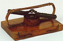
1827年的馬達
1740年,第一個電動馬達是由蘇格蘭僧侶安德魯·戈登(Andrew Gordon)創建的簡單的靜電設備。1827年,匈牙利物理學家安幼思·傑德利克(ÁnyosJedlik)開始嘗試用電磁線圈進行實驗。傑德利克解決一些技術問題後,稱他的設備為「電磁自轉機」。雖然只用於教學目的,但第一款傑德利克的設備已包含今日直流馬達的三個主要組成部分:定子,轉子和換向器。
1835年,美國一位鐵匠湯馬斯·達文波特(Thomas Davenport)製作出世界上第一台能驅動小電車的應用馬達,並在1837年申請了專利。由於主要動力電池成本極高,在商業上不成功,達文波特破產 。一些發明家繼續發展應用馬達,但都遇到了同樣電池發電成本的問題。
1845年,英國物理學家惠斯頓(Wheatstone)申請線性馬達的專利 ,但原理於1960年代才被重視,而設計了實用性的線性馬達,目前已被廣泛在工業上應用。
1870年代初期,世界上最早可商品化的馬達由比利時電機工程師Zenobe Theophile Gamme所發明。1888年,美國著名發明家尼古拉·特斯拉應用法拉第的電磁感應原理,發明交流馬達,即為感應馬達 。
1902年,瑞典工程師丹尼爾森利用特斯拉感應馬達的旋轉磁場觀念 ,發明了同步馬達。1923年,蘇格蘭人James Weir French發明三相可變磁阻型(Variable reluctance)步進馬達。
1962年,藉霍爾元件之助,實用之DC無刷馬達終於問世。1980年代,實用之超音波馬達開始問世。
原理
馬達的旋轉原理的依據為佛來明左手定則或是右手開掌定則,當一導線置放於磁場內,若導線通上電流,則導線會切割磁場線使導線產生移動。電流進入線圈產生磁場,利用電流的磁效應,使電磁鐵在固定的磁鐵內連續轉動的裝置,可以將電能轉換成動能。與永久磁鐵或由另一組線圈所產生的磁場互相作用產生動力。
電動機的種類很多,以基本結構來說,其組成主要由定子和轉子所構成。定子在空間中靜止不動,轉子則可繞軸轉動,由軸承支撐。定子與轉子之間會有一定空氣間隙(氣隙),以確保轉子能自由轉動。機殼(場軛)需要用高導磁係數材料製成,要當作磁路用。
直流馬達的原理是定子不動,轉子依交互作用所產生作用力的方向運動。交流馬達則是定子繞組線圈通上交流電,產生旋轉磁場,旋轉磁場吸引轉子一起作旋轉運動。
此圖中旋轉磁場是由三個不同相位線圈產生的磁場向量形成
就是明證。故而仍舊得入『機電互動』之門也。
─── 《STEM 隨筆︰古典力學︰轉子【五】《電磁學》》
事物之『概念』交織成網,欲深入其一,終得涉獵其餘!
此所以始於『推動者』也︰
電動勢
在電路學裏,電動勢(英語:electromotive force,縮寫為emf)表徵一些電路元件供應電能的特性。這些電路元件稱為「電動勢源 」。電化電池、太陽能電池、燃料電池、熱電裝置、發電機等等,都是電動勢源。電動勢源所供應的能量每單位電荷是其電動勢[1]。假設,電荷  移動經過一個電動勢源後,獲得了能量
  ,則此元件的電動勢定義為
  [2]。通常,這能量是分離正負電荷所做的功,由於這正負電荷被分離至元件的兩端,會出現對應電場與電壓差。
在電磁學裏,電動勢又分為兩種:「感生電動勢」與「動生電動勢」。根據法拉第感應定律,處於含時磁場的閉電路,由於磁場隨著時間而改變,會有感生電動勢出現於閉電路。感生電動勢等於電場沿著閉電路的路徑積分。處於閉電路的帶電粒子會感受到電場,因而產生電流。
移動於磁場的細直導線,其內部會出現動生電動勢。處於這導線的電荷,根據勞侖茲力定律,會感受到勞侖茲力,從而造成正負電荷分離至直棍的兩端。這動作會形成一個電場與伴隨的電場力,抗拒勞侖茲力,直到兩種作用力達成平衡。
歷史
從1825年到1826年之間,格奧爾格·歐姆做了很多有關於電路的實驗。1827年,在他發表的書《直流電路的數學研究》(Die galvanische Kette, mathematisch bearbeitet)裏面,論述了很多這些實驗和從這些實驗中得到的結果,包括著名的「歐姆定律」。歐姆注意到電路所需要的電源是由電池供給的,電池與電路內的各種物理現象應該有密切關係。他推論電池具有某種「驅動力」,能夠驅使電流流動於電路。他將幾個伏打電池串聯在一起,發覺電流與伏打電池的數量成正比。因此,他提出驅動力與電流成正比。這驅動力就是現在的電動勢,在一個簡單的電阻電路裏,電動勢等於電流乘以電阻。
後來,於1831年,麥可·法拉第做了一系列有關電磁感應的實驗,從這些實驗,他發現以下幾點:
於1832年,法拉第又發現,產生於不同導線的感應電流與導線的電導率成正比。由於電導率與電阻成反比,這顯示出感應作用涉及了電動勢,感應電流是由電動勢驅使導線的電荷移動而形成的;而且 ,不論導線是開電路,或是閉電路,都會感應出電動勢[3]。
嚴格定義
當處於平衡狀態時,在一個呈開電路狀態的電動勢源元件(例如,電池)內部,電動勢促使正電荷和負電荷被分離至元件兩端。電荷分離形成的保守性靜電場  所產生的電場力,完全抵銷了產生電動勢
  的作用力。電場 沿著電動勢源的內部路徑,從負端點
  到正端點
到正端點  的積分,與電動勢大小相等,正負相反。電動勢乃是遷移正電荷於電動勢源的內部路徑,從負端點到正端點,抗拒電場 所做的功每單位電荷[4]。以方程式表達,
 ;
;
其中, 是微小線元素向量。
從電動勢源,這正電荷會感受到的電場  ,其與電動勢的關係為
 。(1)
。(1)
對於閉迴路案例,假設閉迴路  所圍住的固定曲面,在這曲面的磁場
  與時間有關,則根據法拉第感應定律,會有感生電動勢 出現於這閉迴路:
 ;
;
其中, 是邊緣為閉迴路 的任意曲面,
 是微小面元素向量,
 是穿過曲面 的磁通量。
電場沿著閉迴路的環流量不會等於零,而會等於感生電動勢[5]:
 ;
;
其中, 是總電場,包括保守性電場 和非保守性電場
  。
。
對於這案例,靜電場並不是總電場的維一的貢獻者。靜電場部分是保守的。靜電場部分沿著閉迴路的電場環流量等於零,只有非保守性電場 會貢獻出感生電動勢:
 ;
;
這定義可以延伸至任意電動勢源和移動的閉迴路 [6](在移動於磁場的閉迴路內部會出現動生電動勢  ):
):
 ;
;
其中, 是有效化學作用力,
 是有效熱作用力,
 是微小線元素的移動速度。
將勞侖茲力方程式代入,
 ;
;
其中, 是勞侖茲力。
由於很難準確的計算出有效化學作用力和有效熱作用力,這方程式只是一個概念方程式。
標記與度量單位
電動勢通常會以希臘字母 標記。
給予一個內部電阻為零的元件,假設電荷 由於移動經過元件,獲得能量 ,則元件的淨電動勢為的獲得的能量每單位電荷  。採用國際單位制,就像其它能量每單位電荷的度量,電動勢的單位是伏特(volt),等價於焦耳/庫侖(joules per coulomb)。
採用厘米-克-秒制,電動勢的單位是靜伏特(statvolt),等價於爾格/靜庫侖(erg per statcoulomb)[7]。
電動勢和路端電壓的關係
理想電動勢源不具有任何內阻,放電與充電不會浪費任何電能。理想電動勢源給出的電動勢與其路端電壓相等。
在實際應用中,電動勢源不可避免地有一定的內阻。實際電動勢源的電阻可以視為一個理想電動勢源串聯一個電阻為內阻的電阻器。內阻的大小取決於電動勢源的大小、化學性質、使用時間、溫度和負載電流。
在通電的閉電路中,內阻相當於一個負載,並且消耗電能。
- 放電電路:在放電電路中,二者關係為
 ,其中
,其中  表示路端電壓,
 表示迴路電流,
 表示內阻。
表示內阻。 - 充電電路:在充電電路中,二者關係為
 ,其中 表示外加充電電源提供給被充電電源兩端的電壓。
在一個呈開電路狀態的電動勢源內部,由於電流為零,電動勢與路端電壓相等。
其次藉著常見『東西』說明,進而能了解
電動勢生成機制
電化電池
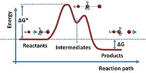
通常的反應途徑會要求初始反應物越過一個能量障壁,進入中間態,最後出現於一個較低能量的狀態。假若涉及到電荷分離,這能量差可能會造成電動勢。更詳細論述,請參閱條目過渡狀態[10]。
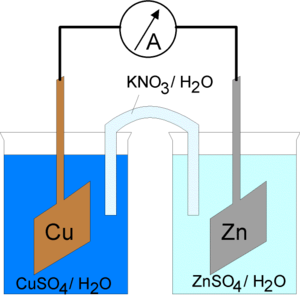
使用KNO3玻璃管型鹽橋的電化電池。
在十九世紀的一大段時間,許多科學家都致力於尋找電池(伽凡尼電池)產生電動勢的機制。最終,瓦爾特·能斯特發現電動勢的作用點是處於電極與電解質之間的接觸面[11]。
分子是一群原子靠著化學鍵連接在一起而形成。這些化學鍵是電子與質子之間相互吸引的電場力。孤立的分子是穩定實體;但當將不同的分子集聚在一起時,有些種類的分子能夠偷取其它分子的電子,造成電荷分離。這種電荷重新分布會改變整個系統的能量,以及分子內部原子的重新組態[12]。
氧化反應是化合價升高,失去電子的反應;還原反應是化合價降低,獲得電子的反應。發生這種電子交換事件的反應稱為氧化還原反應。在電池裏,陽極是發生氧化反應的電極(或者失去電子的電極);而陰極則是發生還原反應的電極(或者獲得電子的電極)。這同樣的物理行為可以從原子本身觀察出來。原子偷取電子的能力稱為電負性[13]
舉例而言,在丹尼耳電池裏,鋅陽極的鋅原子會溶解於硫酸鋅溶液,溶解的鋅原子會遺留其電子於陽極,根據氧化反應(s = 固體陽極,aq = 水溶液):
 。
。
硫酸鋅是一種電解質,在溶液內有可以導電的離子,鋅離子  與硫酸根離子
  。
。
在丹尼爾電池的銅陰極區域,根據還原反應,硫酸銅電解質的銅離子會從陰極獲得電子:
 。
。
電子會通過外電路(示意圖內的檢流計),而硫酸根離子會通過鹽橋,這樣,可以保持電荷平衡。當反應進行時,鋅陽極會緩慢的溶解,而銅陰極表面會被電鍍。假若外電路被斷開,由於電荷分離產生的電場會抗拒兩個電極之間的電動勢,反應會停止。
,那個『概念方程式』在說『什麼』。然後認識
動生電動勢
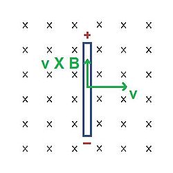
一條長度為  的細直導線以速度 移動於磁場 。
許多發電機的基本運作原理涉及動生電動勢概念。移動於磁場的導線,其內部會出現電動勢,稱為「動生電動勢」。如圖右所示[16],假設一條長度為 的細直導線,以速度 移動於磁場 。磁場 以箭尾或叉叉表示。思考在這導線內的電荷  ,根據勞侖茲力定律,會感受到勞侖茲力
  :
:
 。
。
在這裡,勞侖茲力也是磁場力。因為感受到這磁場力,正電荷會往導線的上端移動,負電荷會往導線的下端移動。在穩定平衡狀態,這動作會形成一個電場 :
 。
。
如同先前方程式(1)的定義,電動勢定義為,遷移正電荷於導線路徑  ,從負端點到正端點,抗拒電場 所做的功每單位電荷,以方程式表示為
 。
。
對於這案例,假若達到穩定平衡狀態,則電流等於零。假設載流導線與其他元件連結成閉電路,則會因為動生電動勢而產生電流。例如,將一個電阻  與導線的兩端相連結,則流過電阻的電流 為
 。
。
同時及於
反電動勢
反電動勢(counter emf或back emf)是指有反抗電流通過趨勢的電動勢,其本質上屬於感應電動勢。[1]
電動機轉動時,線圈中也會產生感應電動勢,這個感應電動勢總要削弱電源電動勢的作用,這個感應電動勢即為反電動勢。它的作用是阻礙線圈的轉動。如果要使線圈維持原來的轉動,電源就要向電動機提供能量,從而實現電能轉化為其它形式的能。
起動電流
電動機及變壓器在開啟的時候,沒有反電動勢,根據V=IR,電流會很大。因此,有相關法例規定電動機的起動電流,避免起動電流過大而導致電壓驟降,影響其他設備和其他用戶。大功率電動機對供電系統影響較大,規管更嚴格。
注意事項
如果電動機工作中由於機械阻力過大而停止轉動,這時沒有了反電動勢,電阻很小的線圈直接連在電源的兩端,電流會很大,時間長了很可能把電動機燒毀。
自能通曉
DC motor
A DC motor is any of a class of rotary electrical machines that converts direct current electrical energy into mechanical energy. The most common types rely on the forces produced by magnetic fields. Nearly all types of DC motors have some internal mechanism, either electromechanical or electronic, to periodically change the direction of current flow in part of the motor.
DC motors were the first type widely used, since they could be powered from existing direct-current lighting power distribution systems. A DC motor’s speed can be controlled over a wide range, using either a variable supply voltage or by changing the strength of current in its field windings. Small DC motors are used in tools, toys, and appliances. The universal motor can operate on direct current but is a lightweight brushed motor used for portable power tools and appliances. Larger DC motors are used in propulsion of electric vehicles, elevator and hoists, or in drives for steel rolling mills. The advent of power electronics has made replacement of DC motors with AC motors possible in many applications.
Brushed
Main article: Brushed DC electric motor
A brushed DC electric motor generating torque from DC power supply by using an internal mechanical commutation. Stationary permanent magnets form the stator field. Torque is produced by the principle that any current-carrying conductor placed within an external magnetic field experiences a force, known as Lorentz force. In a motor, the magnitude of this Lorentz force (a vector represented by the green arrow), and thus the output torque,is a function for rotor angle, leading to a phenomenon known astorque ripple) Since this is a two-pole motor, the commutator consists of a split ring, so that the current reverses each half turn ( 180 degrees).
The brushed DC electric motor generates torque directly from DC power supplied to the motor by using internal commutation, stationary magnets (permanent or electromagnets), and rotating electromagnets.
Advantages of a brushed DC motor include low initial cost, high reliability, and simple control of motor speed. Disadvantages are high maintenance and low life-span for high intensity uses. Maintenance involves regularly replacing the carbon brushes and springs which carry the electric current, as well as cleaning or replacing the commutator. These components are necessary for transferring electrical power from outside the motor to the spinning wire windings of the rotor inside the motor.
Brushes are usually made of graphite or carbon, sometimes with added dispersed copper to improve conductivity. In use, the soft brush material wears to fit the diameter of the commutator, and continues to wear. A brush holder has a spring to maintain pressure on the brush as it shortens. For brushes intended to carry more than an ampere or two, a flying lead will be molded into the brush and connected to the motor terminals. Very small brushes may rely on sliding contact with a metal brush holder to carry current into the brush, or may rely on a contact spring pressing on the end of the brush. The brushes in very small, short-lived motors, such as are used in toys, may be made of a folded strip of metal that contacts the commutator.
Brushless
Typical brushless DC motors use one or more permanent magnets in the rotor and electromagnets on the motor housing for the stator. A motor controller converts DC to AC. This design is mechanically simpler than that of brushed motors because it eliminates the complication of transferring power from outside the motor to the spinning rotor. The motor controller can sense the rotor’s position via Hall effect sensors or similar devices and can precisely control the timing, phase, etc., of the current in the rotor coils to optimize torque, conserve power, regulate speed, and even apply some braking. Advantages of brushless motors include long life span, little or no maintenance, and high efficiency. Disadvantages include high initial cost, and more complicated motor speed controllers. Some such brushless motors are sometimes referred to as “synchronous motors” although they have no external power supply to be synchronized with, as would be the case with normal AC synchronous motors.
耶?