假使人還不能知道『自我』 Self 是什麼?那麼人能找到榮格所說的『自性』嗎?就像一股『味道』帶出了『情懷』,漸漸的發覺那是早年的『記憶』!有種特殊的『感覺』!!如是一個記不清童年的我,能有什麼不同的『聯想』呢??
……
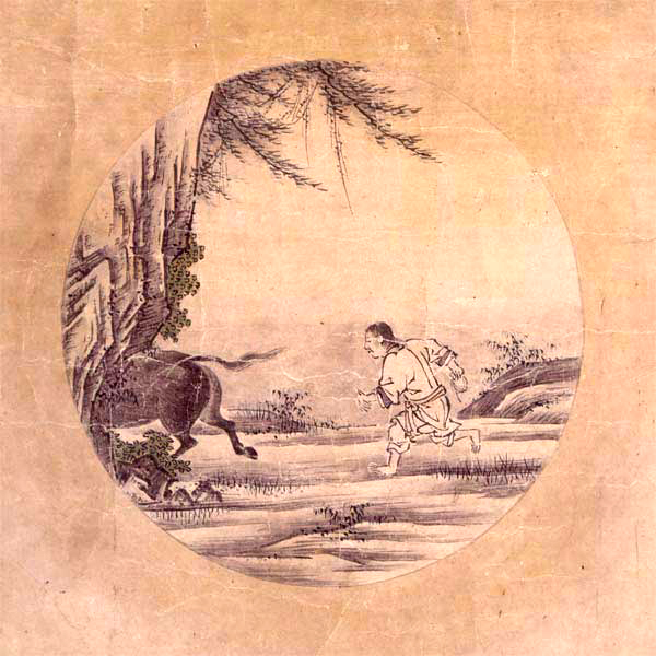
因此縱聞古有廓庵十牛圖
1) 尋牛
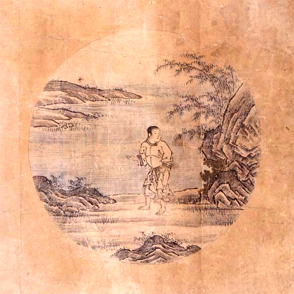
2) 見跡
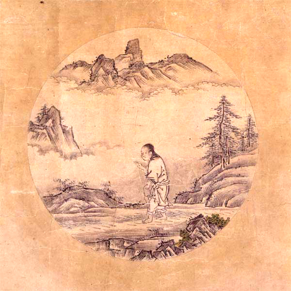
3) 見牛
4) 得牛
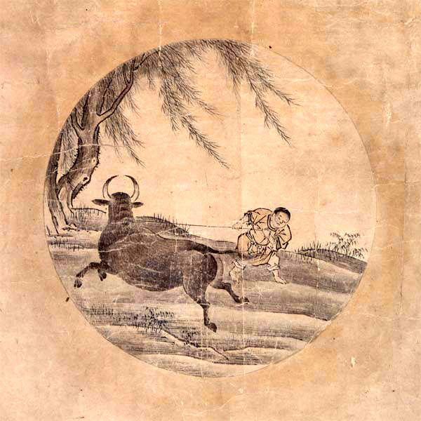
5) 牧牛
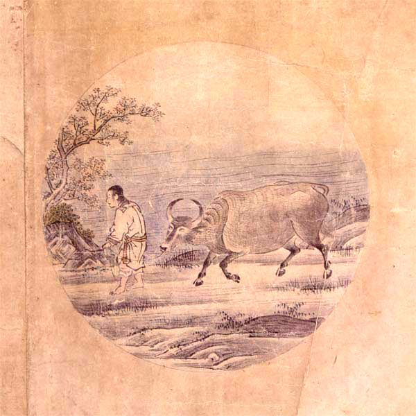
6) 騎牛歸家
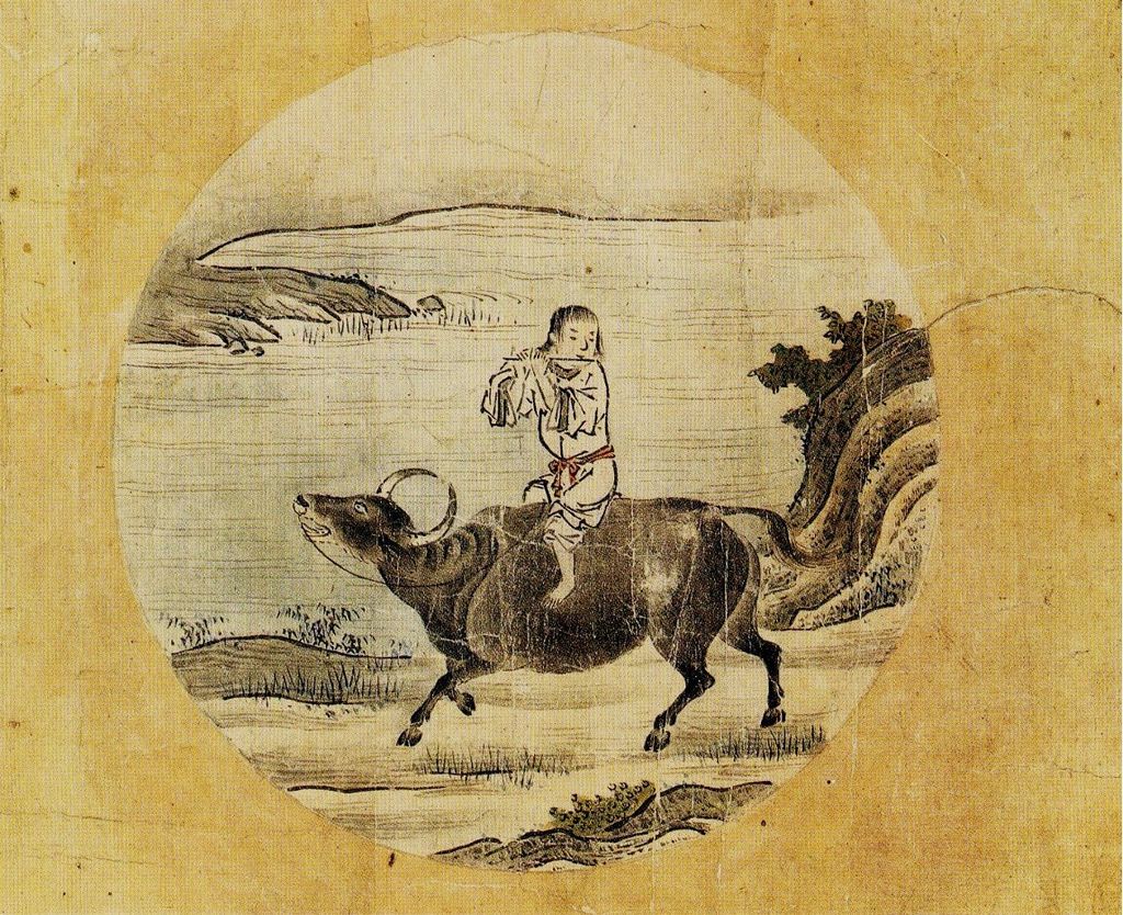
7) 忘牛存人
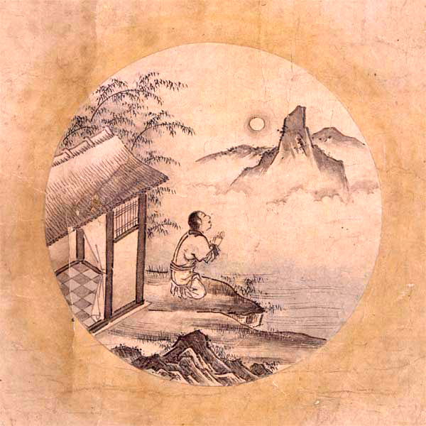
8) 人牛俱忘
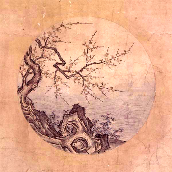
9) 返本還源
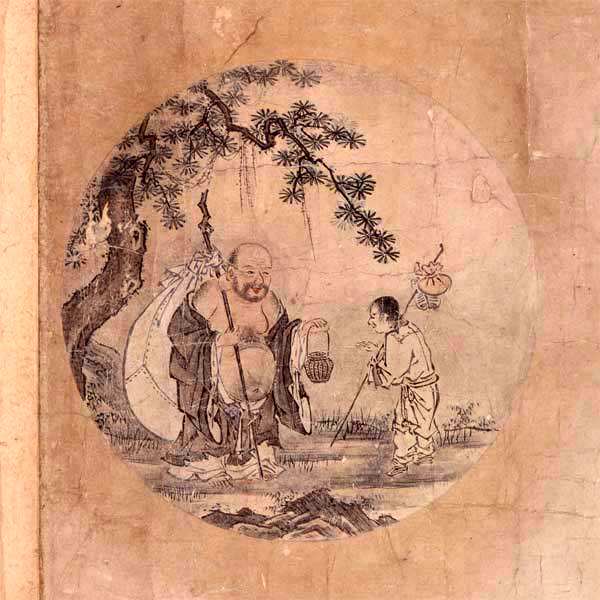
10) 入鄽垂手
果能『轉態』度一生??
狀態轉移矩陣
狀態轉移矩陣(state-transition matrix)是控制理論中的矩陣,是時間  和初始時間
和初始時間  的函數,可以將時間 的狀態向量
  和此矩陣相乘,得到時間 時的狀態向量 。狀態轉移矩陣可以用來找線性動態系統的通解。
線性系統的解
 ,
,
其中  為系統狀態,
  為輸入信號,而
  為時間 時的初始條件。利用狀態轉移矩陣
  ,其解如下[1][2]:

第一項為零輸入響應(zero-input response),第二項為零狀態響應(zero-state response)。
若系統是時不變系統,可以將  定義為
定義為

在時變系統的例子中,可能有許多不同的函數滿足上述條件,而解和系統的結構有關。在分析時變系統的解之前,需要先確定其狀態轉移矩陣。
─── 《萬象在說話︰心理是聯想網絡?》
數已至十,又是歸零進位之時!宜乎尋氣味相投友朋共修耶?
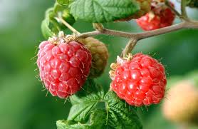
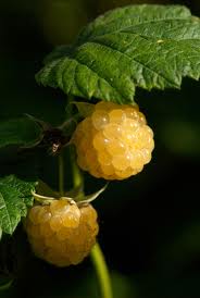

五官 ── 眼、耳、鼻、舌、身 ── 從心,各有『利』與『鈍』。有的人『不聽講』自己看書『看不懂』;又有人『一目十行』,可以『既讀即解』;還有的人非得『親為』否則『不解』。難道說『鼻』與『舌』就果真或與『讀書無緣』?俗話說︰『氣味相投』自然朋比;『把酒飛斝』無非道友。學習的過程中,如果有志同道合的『朋友』,彼此切磋琢磨,想必更能日行千里,事半功倍吧!!
莊子講『庖丁解牛』的故事,講到庖丁功夫之深厚,竟然能讓『解牛』不知其死,真真的是出神入化的好勒!!科學教育的重要性在於求『真』,然而需要了解的是,世界有『價值』的不只是『真』而已,也許說還有著『善』與『美』吧。曾經有一位西方哲人說道︰所謂『善』就是把『真』的事,用『美』得方式呈現;古時或有另一位東方覺者談起︰天大、地大、人亦大 ──
【佚名詩】
大地藏無盡,
勤勞資有生;
念哉斯意厚,
努力事春耕。
──,
大人者不失其『赤子之心』。
科學的方法在於『實驗』,不斷驗證『人以為知』之事,而這個 方法要求『人人都能』與『時時都可』,是嚴格的『事實』立論的基石,故可以說是強調『他証性』;然而人世間『經驗』的廣褒,自有『如人飲水』『自証』之事,與『朋比道友』『互証』之實。
相互切磋琢磨文章︰
Andrew Gibiansky :: Math → [Code]
Quadcopter Dynamics and Simulation
Introduction
A helicopter is a flying vehicle which uses rapidly spinning rotors to push air downwards, thus creating a thrust force keeping the helicopter aloft. Conventional helicopters have two rotors. These can be arranged as two coplanar rotors both providing upwards thrust, but spinning in opposite directions (in order to balance the torques exerted upon the body of the helicopter). The two rotors can also be arranged with one main rotor providing thrust and a smaller side rotor oriented laterally and counteracting the torque produced by the main rotor. However, these configurations require complicated machinery to control the direction of motion; a swashplate is used to change the angle of attack on the main rotors. In order to produce a torque the angle of attack is modulated by the location of each rotor in each stroke, such that more thrust is produced on one side of the rotor plane than the other. The complicated design of the rotor and swashplate mechanism presents some problems, increasing construction costs and design complexity.
A quadrotor helicopter (quadcopter) is a helicopter which has four equally spaced rotors, usually arranged at the corners of a square body. With four independent rotors, the need for a swashplate mechanism is alleviated. The swashplate mechanism was needed to allow the helicopter to utilize more degrees of freedom, but the same level of control can be obtained by adding two more rotors.
The development of quadcopters has stalled until very recently, because controlling four independent rotors has proven to be incredibly difficult and impossible without electronic assistance. The decreasing cost of modern microprocessors has made electronic and even completely autonomous control of quadcopters feasible for commercial, military, and even hobbyist purposes.
Quadcopter control is a fundamentally difficult and interesting problem. With six degrees of freedom (three translational and three rotational) and only four independent inputs (rotor speeds), quadcopters are severely underactuated. In order to achieve six degrees of freedom, rotational and translational motion are coupled. The resulting dynamics are highly nonlinear, especially after accounting for the complicated aerodynamic effects. Finally, unlike ground vehicles, helicopters have very little friction to prevent their motion, so they must provide their own damping in order to stop moving and remain stable. Together, these factors create a very interesting control problem. We will present a very simplified model of quadcopter dynamics and design controllers for our dynamics to follow a designated trajectory. We will then test our controllers with a numerical simulation of a quadcopter in flight.
Quadcopter Dynamics
We will start deriving quadcopter dynamics by introducing the two frames in which will operate. The inertial frame is defined by the ground, with gravity pointing in the negative zz direction. The body frame is defined by the orientation of the quadcopter, with the rotor axes pointing in the positive zz direction and the arms pointing in the xx and yy directions.
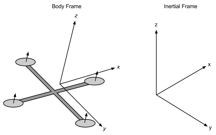
Quadcopter Body Frame and Inertial Frame
………
Conclusion
We derived equations of motion for a quadcopter, starting with the voltage-torque relation for the brushless motors and working through the quadcopter kinematics and dynamics. We ignored aerodynamical effects such as blade-flapping and non-zero free stream velocity, but included air friction as a linear drag force in all directions. We used the equations of motion to create a simulator in which to test and visualize quadcopter control mechanisms.
We began with a simple PD controller. Although the PD controller worked, it left a significant steady-state error. In order to decrease the steady-state error, we added an integral term in order to create a PID controller. We tested the PID controller (with minor modifications to prevent integral wind-up) and found that it was better at preventing steady-state error than the PD controller when presented with the same disturbances and using the same proportional and derivative gains. We also found that tuning the PID controller was difficult, and would often lead to an unstable system for unknown reasons. In order to avoid the difficulty of PID tuning and find the optimal set of parameters, we used a gradient-descent based extremum seeking method in order to numerically estimate gradients of a cost function in PID-parameter space and iteratively choose a set of parameters to minimize the cost function. We found that the resulting controller was significantly better than the one using manually turned parameters.
可將四軸飛行器送上青天☆
讓它表演特技呦☆☆
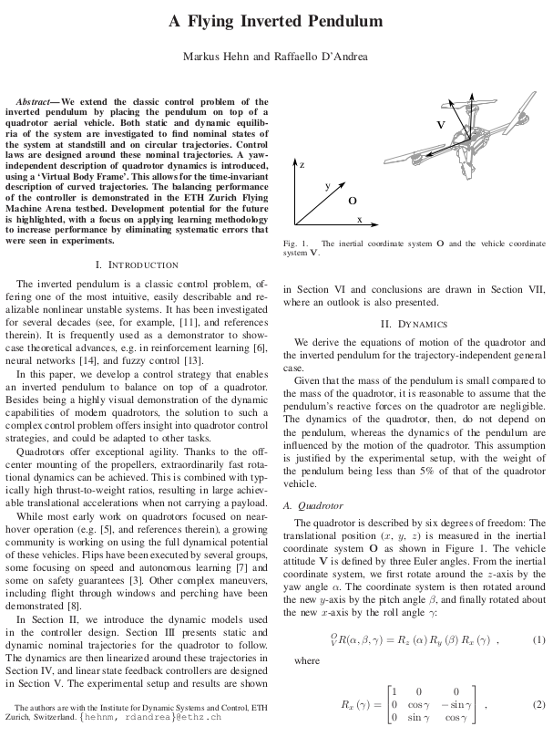
Markus Hehn and Raffaello D’Andrea