祇是閱讀維基百科
Brushed DC electric motor
A brushed DC motor is an internally commutated electric motor designed to be run from a direct current power source. Brushed motors were the first commercially important application of electric power to driving mechanical energy, and DC distribution systems were used for more than 100 years to operate motors in commercial and industrial buildings. Brushed DC motors can be varied in speed by changing the operating voltage or the strength of the magnetic field. Depending on the connections of the field to the power supply, the speed and torque characteristics of a brushed motor can be altered to provide steady speed or speed inversely proportional to the mechanical load. Brushed motors continue to be used for electrical propulsion, cranes, paper machines and steel rolling mills. Since the brushes wear down and require replacement, brushless DC motors using power electronic devices have displaced brushed motors from many applications.
詞條,藉著
Simple two-pole DC motor
圖示︰
The following graphics illustrate a simple, two-pole, brushed, DC motor.
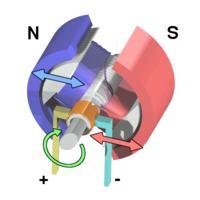
A simple DC electric motor. When the coil is powered, a magnetic field is generated around the armature. The left side of the armature is pushed away from the left magnet and drawn toward the right, causing rotation.
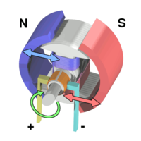
The armature continues to rotate.
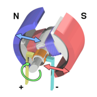
When the armature becomes horizontally aligned, the torque becomes zero. At this point, the commutator reverses the direction of current through the coil, reversing the magnetic field.
The process then repeats.
明白設計之問題與想法︰
When a current passes through the coil wound around a soft iron core, the side of the positive pole is acted upon by an upwards force, while the other side is acted upon by a downward force. According to Fleming’s left hand rule, the forces cause a turning effect on the coil, making it rotate. To make the motor rotate in a constant direction, “direct current” commutators make the current reverse in direction every half a cycle (in a two-pole motor) thus causing the motor to continue to rotate in the same direction.
A problem with the motor shown above is that when the plane of the coil is parallel to the magnetic field—i.e. when the rotor poles are 90 degrees from the stator poles—the torque is zero. In the pictures above, this occurs when the core of the coil is horizontal—the position it is just about to reach in the last picture on the right. The motor would not be able to start in this position. However, once it was started, it would continue to rotate through this position by momentum.
There is a second problem with this simple pole design. At the zero-torque position, both commutator brushes are touching (bridging) both commutator plates, resulting in a short-circuit. The power leads are shorted together through the commutator plates, and the coil is also short-circuited through both brushes (the coil is shorted twice, once through each brush independently). Note that this problem is independent of the non-starting problem above; even if there were a high current in the coil at this position, there would still be zero torque. The problem here is that this short uselessly consumes power without producing any motion (nor even any coil current.) In a low-current battery-powered demonstration this short-circuiting is generally not considered harmful. However, if a two-pole motor were designed to do actual work with several hundred watts of power output, this shorting could result in severe commutator overheating, brush damage, and potential welding of the brushes—if they were metallic—to the commutator. Carbon brushes, which are often used, would not weld. In any case, a short like this is very wasteful, drains batteries rapidly and, at a minimum, requires power supply components to be designed to much higher standards than would be needed just to run the motor without the shorting.
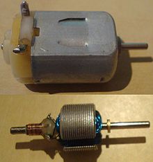
The inside of a miniature DC motor as would be found in a toy.
One simple solution is to put a gap between the commutator plates which is wider than the ends of the brushes. This increases the zero-torque range of angular positions but eliminates the shorting problem; if the motor is started spinning by an outside force it will continue spinning. With this modification, it can also be effectively turned off simply by stalling (stopping) it in a position in the zero-torque (i.e. commutator non-contacting) angle range. This design is sometimes seen in homebuilt hobby motors, e.g. for science fairs and such designs can be found in some published science project books. A clear downside of this simple solution is that the motor now coasts through a substantial arc of rotation twice per revolution and the torque is pulsed. This may work for electric fans or to keep a flywheel spinning but there are many applications, even where starting and stopping are not necessary, for which it is completely inadequate, such as driving the capstan of a tape transport, or any instance where to speed up and slow down often and quickly is a requirement. Another disadvantage is that, since the coils have a measure of self inductance, current flowing in them cannot suddenly stop. The current attempts to jump the opening gap between the commutator segment and the brush, causing arcing.
Even for fans and flywheels, the clear weaknesses remaining in this design—especially that it is not self-starting from all positions—make it impractical for working use, especially considering the better alternatives that exist. Unlike the demonstration motor above, DC motors are commonly designed with more than two poles, are able to start from any position, and do not have any position where current can flow without producing electromotive power by passing through some coil. Many common small brushed DC motors used in toys and small consumer appliances, the simplest mass-produced DC motors to be found, have three-pole armatures. The brushes can now bridge two adjacent commutator segments without causing a short circuit. These three-pole armatures also have the advantage that current from the brushes either flows through two coils in series or through just one coil. Starting with the current in an individual coil at half its nominal value (as a result of flowing through two coils in series), it rises to its nominal value and then falls to half this value. The sequence then continues with current in the reverse direction. This results in a closer step-wise approximation to the ideal sinusoidal coil current, producing a more even torque than the two-pole motor where the current in each coil is closer to a square wave. Since current changes are half those of a comparable two-pole motor, arcing at the brushes is consequently less.
If the shaft of a DC motor is turned by an external force, the motor will act like a generator and produce an Electromotive force (EMF). During normal operation, the spinning of the motor produces a voltage, known as the counter-EMF (CEMF) or back EMF, because it opposes the applied voltage on the motor. The back EMF is the reason that the motor when free-running does not appear to have the same low electrical resistance as the wire contained in its winding. This is the same EMF that is produced when the motor is used as a generator (for example when an electrical load, such as a light bulb, is placed across the terminals of the motor and the motor shaft is driven with an external torque). Therefore, the total voltage drop across a motor consists of the CEMF voltage drop, and the parasitic voltage drop resulting from the internal resistance of the armature’s windings. The current through a motor is given by the following equation:

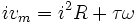
The mechanical power produced by the motor is given by:

As an unloaded DC motor spins, it generates a backwards-flowing electromotive force that resists the current being applied to the motor. The current through the motor drops as the rotational speed increases, and a free-spinning motor has very little current. It is only when a load is applied to the motor that slows the rotor that the current draw through the motor increases.
於有刷 DC 電動機或能有一定的認識也!不過若缺少整體性描述,恐難以貫通『機‧電』交界耶?
Torque and speed of a DC motor
A DC motor‘s speed and torque characteristics vary according to three different magnetization sources, separately excited field, self-excited field or permanent-field, which are used selectively to control the motor over the mechanical load’s range. Self-excited field motors can be series, shunt, or compound wound connected to the armature.
Basic properties
Define
- Eb, induced or counter EMF (V)
- Ia, armature current (A)
- kb, counter EMF equation constant
- kn, speed equation constant
- kT, torque equation constant
- n, armature frequency (rpm)
- Rm, motor resistance (Ω)
- T, motor torque (Nm)
- Vm, motor input voltage (V)
- Φ, machine’s total flux (Wb)
Counter EMF equation
The DC motor’s counter emf is proportional to the product of the machine’s total flux strength and armature speed:
- Eb = kb Φ n[6]
Voltage balance equation
The DC motor’s input voltage must overcome the counter emf as well as the voltage drop created by the armature current across the motor resistance, that is, the combined resistance across the brushes, armature winding and series field winding, if any:
Torque equation
The DC motor’s torque is proportional to the product of the armature current and the machine’s total flux strength:[9][10][11]

where
- kT = kb/2π
Speed equation
Since
- n = Eb/kb Φ and
- Vm = Eb + Rm Ia

where
- kn = 1/kb
故先請讀者耕耘哩☆
Brushed DC Motor Theory
Introduction
The specific type of motor we are addressing is the permanent magnet brushed DC motor (PMDC). These motors have two terminals. Applying a voltage across the terminals results in a proportional speed of the output shaft in steady state.
There are two pieces to the motor: 1) stator and 2) rotor. The stator includes the housing, permanent magnets, and brushes. The rotor consists of the output shaft, windings and commutator. The image below shows a cut-away view of a Maxon motor. Note this picture has a gearbox and encoder attached to the motor.

Motor Physics
The forces inside a motor that cause the rotor to rotate are called Lorentz Forces. If an electron is moving through a magnetic field, it experiences a force. If we have a current  passing through a wire in a magnetic field
  , the wire experiences a force
  proportional to the cross product of the current (expressed as a vector, including the direction of flow) and the magnetic field:
 |
You can easily find the direction of this force using the Right Hand Rule. The Right Hand Rule states that if you point your right hand’s index finger along the direction of current, I, and your middle finger in the direction of magnetic flux, B, the direction of force is along the thumb. See the picture below.

Now, imagine this single wire is replaced with a loop of wire. Between the magnets’ poles, this looks like two wires with current flowing in opposite directions. The forces on the wires cause the loop to rotate.

A coil consists of many such loops, and it is attached to the rotor and rotates. As it does so, the magnitude and direction of the forces on the wires remain approximately constant. However, the resultant torque varies with the angle. Look at the picture below. When the coil starts, there is maximum torque. As the coil moves, the moment arm is reduced and the torque decreases. Finally, when the coil is vertical (in the picture), there is no torque.

To keep a nearly constant torque on the rotor, we can do two things. First, we can reverse the current through the coil every half turn. So instead of an alternating torque like the one in the first figure below, the torque is always in the same direction. Also, additional coils can be used. When these coils are offset at different angles around the motor, the resultant torque becomes the sum of the colored torque curves in the figure below. The resultant torque is always greater than zero, but is not constant. This angle-dependent variation is called torque ripple.

The process of switching current direction is called commutation. To switch the direction of curent, brushed DC motors use brushes and commutators. The brushes are attached to the motor’s two external wires, and the commutator segments slide over the brushes so that current through the coils switches at appropriate angles. Commutation can also be done electronically (see Brushless DC Motors). The following diagram shows how brushes and commutators work. A real commutator must have at least three segments.

Equations

We start by writing the equation for conservation of energy in the motor. The power is input as electrical power,  and the motor converts that to mechanical power,
  . However, some of the power is lost as heat,
  , due to ohmic heating of the motor coils.

We can re-write this in terms of electrical and mechanical quantities as
where vm is the voltage across the motor terminals, i is the current through the motor, τ is the torque produced by the motor, and ω is its angular velocity.
The wire coils have both a resistance, R, and an inductance, L. The motor’s defining equation is
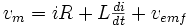

 , which depends on the motor design. (My preference is to use SI units, using radians-per-second for angular velocity and volt-seconds/radians for the electrical constant and radians/volt-seconds for the speed constant. But speed constants are usually given in different units, and rpms are the most common angular velocity unit in motor data sheets.) The back-emf term indicates that any motor is also a generator: if we spin the motor shaft, we read a voltage at the motor terminals. This is how dams create hydroelectric power.
The torque generated by the motor is proportional to the current through the windings, where the constant of proportionality is called the torque constant kt or motor constant kM:

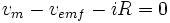
We are often interested in the steady-state operating characteristics of a motor, when the current i is constant. The term Ldi / dt becomes zero, and we get
Datasheets and Speed-Torque Curves
The datasheet below is for the Maxon motor available in the Mechatronics Lab. That motor also has an integrated 6:1 gearhead and a 100 line encoder. The motor is rated at 6 W, which is approximately the input power (voltage times current) when the motor is operated at the nominal voltage (24 V) and maximum continuous torque, where the current is approximately 240 mA.

1. Nominal voltage: The recommended maximum voltage across the motor terminals, and the voltage for which the speed-torque curve (below) is plotted. The motor can be powered with less or more voltage, but higher voltage should be used with care, to prevent the motor coils from overheating due to ohmic (resistive) heating.
2. No load speed,  : The speed of the motor powered by the nominal voltage when the motor provides zero torque.
3. No load current: The current required to spin the motor at the no load condition (i.e., the current needed to provide the torque necessary to overcome friction).
4. Nominal speed: The speed of the motor at the maximum continuous torque.
5. Nominal torque (max continuous torque): The maximum torque the motor can provide continuously without overheating.
6. Nominal current (max continuous current): The current that yields the maximum continuous torque. This maximum is determined by thermal characteristics of the motor. The power dissipated by the motor as heat is i2R. Larger currents are acceptable intermittently, but large continuous currents may cause the motor to overheat.
7. Stall torque,  : The maximum torque achievable by the motor at the nominal voltage. This torque is achieved at zero velocity (stall).
8. Starting current,  : The current through the motor at zero velocity, equal to the nominal voltage divided by the terminal resistance. Also called the stall current.
9. Max efficiency: The maximum efficiency of the motor in converting electrical power to mechanical power. This maximum efficiency typically occurs at high speed and low torque; the efficiency is zero at zero speed and zero torque, since the mechanical power is τω.
10. Terminal resistance  : The resistance of the motor windings.
11. Terminal inductance  : The inductance of the motor windings.
12. Torque (or motor) constant,  or
or  : The constant of proportionality relating current to torque. In SI units (Newton-meters per amp), the torque constant is equivalent to the inverse of the speed constant in SI units (radians per volt-second).
13. Speed constant,  (which is the inverse of the electrical constant ): The constant of proportionality relating speed to voltage. Equivalent to the inverse of the torque constant when expressed in SI units.
14. Speed/torque gradient: A representation of the slope of the speed-torque curve (see graph below), approximately equal to the no load speed divided by the stall torque.
15. Mechanical time constant: The time it takes the unloaded motor to reach 63% of its no load speed under a constant voltage, starting from rest. Proportional to the inertia of the rotor and inversely proportional to the square of the the torque constant.
16. Rotor inertia: The inertia of the rotating element (the rotor) about the axis of rotation.
Much of the data sheet can be expressed in the speed-torque curve, plotted for the constant nominal voltage (below). The mechanical power output is the product of the torque and the speed, and is maximized at half the maximum speed and torque.

Often you need higher torques but lower speeds in your application. In this case, you can add a gearbox to the motor, as discussed in Choosing a Motor and Gearing Combination.