釐清問題是避免不必要之紛爭解決問題的第一步◎
如果仔細閱讀
一段 Q&A 文本︰
Undervoltage warning despite decent power supply
Question
I found some related questions about this, yet no answer.
Using a freshly bought “5V/2.1A” rated power supply, I get undervoltage warning square on both my Raspberry3s. Although i measure 4.75V (at the USB ports).
I feel like this should not happen.
Answers
The APX803 chip (which monitors voltage) triggers at 4.63±0.07V.
This is an instantaneous level, whereas your meter will show average. Even assuming your meter is correctly calibrated the trigger may fire if the load varies. The visual trigger has a 3 sec so it will show even if the average is 4.75V (which is already at the lower end of the tolerance range).
The Pi3 actually has a well engineered power circuit, and the SOC will continue to function even if the input voltage is below spec. The same may not be true of the peripherals.
The addition of WiFi and Bluetooth, as well as the faster processor means the Pi3 is more prone to these issues than the Pi2.
Unfortunately the Pi cannot compensate for inadequate power supplies. There are very many of these – I have a few myself, although not as bad as 4.75V.
If you use a cable to connect your PSU to the Pi (if it does not have an integrated lead) you may want to try different leads. Many of the cheaper cables have excessive voltage drop – I actually make my own with decent sized wire.
One of the major causes of problem is high powered peripherals e.g. HDD etc. I suggest you use an external hub if you use these (as do most of us).
It is actually quite simple to design a PSU which would meet the Pi spec, but I couldn’t do it for less than $20 which most of the commercial units do. These are really designed to charge smartphones, which they do adequately.
I have tested a number of PSU (with a dummy load) and have yet to find one which actually delivers the rated voltage at the rated current.
The only way to deliver the rated voltage is to start with slightly higher voltage to compensate for the inevitable voltage drop. That’s why so many adapters are listed at 5.1V or 5.2V. You can minimize the voltage drop by using a lower resistance power cable, as mentioned above. The best cable in this case can be found by searching for “USB charger cable” which typically has heavier gauge wire (18AWG or 20AWG) and is shorter in length. Note that these charge-only cables do not contain data wires, as they’re not needed, so you can’t use them for a general purpose USB data connection. – PhilM Jun 4 ’16 at 4:39
其中有多個『名詞』需要『確定所指』︰
‧ 一般 AC Adapter 規格︰ 5V/2A
‧ 滿足 USB 規範︰ 4.75V
‧ 偵測低電壓樹莓派方式︰ 
‧ 樹莓派 3B 電源供應設計品質
‧ 務須使用 5.1V 或 5.2V 電源供應器
‧ ……
同時查看樹莓派基金會官網說明︰
POWER SUPPLY
The Raspberry Pi 3 is powered by a +5.1V micro USB supply. Exactly how much current (mA) the Raspberry Pi requires is dependent on what you connect to it. We have found that purchasing a 2.5A power supply from a reputable retailer will provide you with ample power to run your Raspberry Pi. You can purchase the official Raspberry Pi Power Supply from our website, and you can learn more about the differing power requirements of the various models of the Raspberry Pi on our FAQ page.
Typically, the model B uses between 700-1000mA depending on what peripherals are connected; the model A can use as little as 500mA with no peripherals attached. The maximum power the Raspberry Pi can use is 1 Amp. If you need to connect a USB device that will take the power requirements above 1 Amp, then you must connect it to an externally-powered USB hub.
The power requirements of the Raspberry Pi increase as you make use of the various interfaces on the Raspberry Pi. The GPIO pins can draw 50mA safely, distributed across all the pins; an individual GPIO pin can only safely draw 16mA. The HDMI port uses 50mA, the camera module requires 250mA, and keyboards and mice can take as little as 100mA or over 1000mA! Check the power rating of the devices you plan to connect to the Pi and purchase a power supply accordingly.
Backpowering
Backpowering occurs when USB hubs do not provide a diode to stop the hub from powering against the host computer. Other hubs will provide as much power as you want out each port. Please also be aware that some hubs will backfeed the Raspberry Pi. This means that the hubs will power the Raspberry Pi through its USB cable input cable, without the need for a separate micro-USB power cable, and bypass the voltage protection. If you are using a hub that backfeeds to the Raspberry Pi and the hub experiences a power surge, your Raspberry Pi could potentially be damaged.
也許思思『漣波』 ripple ︰
AC adapter
An AC adapter, AC/DC adapter, or AC/DC converter[1] is a type of external power supply, often enclosed in a case similar to an AC plug. Other common names include plug pack, plug-in adapter, adapter block, domestic mains adapter, line power adapter, wall wart, power brick, and power adapter. Adapters for battery-powered equipment may be described as chargers or rechargers (see also battery charger). AC adapters are used with electrical devices that require power but do not contain internal components to derive the required voltage and power from mains power. The internal circuitry of an external power supply is very similar to the design that would be used for a built-in or internal supply.
External power supplies are used both with equipment with no other source of power and with battery-powered equipment, where the supply, when plugged in, can sometimes charge the battery in addition to powering the equipment.
Use of an external power supply allows portability of equipment powered either by mains or battery without the added bulk of internal power components, and makes it unnecessary to produce equipment for use only with a specified power source; the same device can be powered from 120 VAC or 230 VAC mains, vehicle or aircraft battery by using a different adapter. Another advantage of these designs can be increased safety; as the hazardous 120 or 240 volt mains power is transformed to a lower safer voltage at the wall outlet, and the appliance which is handled by the user is powered by this lower voltage.
Modes of operation
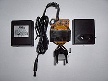
An AC adapter disassembled to reveal a simple, unregulated linear DC supply circuit: a transformer, four diodes in a bridge rectifier, and anelectrolytic capacitor to smooth the waveform
Originally, most AC/DC adapters were linear power supplies, containing a transformer to convert the mains electricity voltage to a lower voltage, a rectifier to convert it to pulsating DC, and a filter to smooth the pulsating waveform to DC, with residual ripple variations small enough to leave the powered device unaffected. Size and weight of the device was largely determined by the transformer, which in turn was determined by the power output and mains frequency. Ratings over a few watts made the devices too large and heavy to be physically supported by a wall outlet. The output voltage of these adapters varied with load; for equipment requiring a more stable voltage, linear voltage regulator circuitry was added. Losses in the transformer and the linear regulator were considerable; efficiency was relatively low, and significant power dissipated as heat even when not driving a load.
Early in the twenty-first century, switched-mode power supplies (SMPSs) became almost ubiquitous for this purpose. Mains voltage is rectified to a high direct voltage driving a switching circuit, which contains a transformer operating at a high frequency and outputs direct current at the desired voltage. The high-frequency ripple is more easily filtered out than mains-frequency. The high frequency allows the transformer to be small, which reduces its losses; and the switching regulator can be much more efficient than a linear regulator. The result is a much more efficient, smaller, and lighter device. Safety is ensured, as in the older linear circuit, because a transformer still provides galvanic isolation.
A linear circuit must be designed for a specific, narrow range of input voltages (e.g., 220–240 VAC) and must use a transformer appropriate for the frequency (usually 50 or 60 Hz), but a switched-mode supply can work efficiently over a very wide range of voltages and frequencies; a single 100–240 VAC unit will handle almost any mains supply in the world.
However, unless very carefully designed and using suitable components, switching adapters are more likely to fail than the older type, due in part to complex circuitry and the use of semiconductors. Unless designed well, these adapters may be easily damaged by overloads, even transient ones, which can come from lightning, brief mains overvoltage (sometimes caused by an incandescent light on the same power circuit failing), component degradation, etc. A very common mode of failure is due to the use of electrolytic capacitors whose equivalent series resistance (ESR) increases with age; switching regulators are very sensitive to high ESR (the older linear circuit also used electrolytic capacitors, but the effect of degradation is much less dramatic). Well-designed circuits pay attention to the ESR, ripple current rating, pulse operation, and temperature rating of capacitors.[2]
想想『USB』標準︰
USB (Physical)
This article provides information about the physical aspects of Universal Serial Bus, USB: connectors, cabling, and power. The initial versions of the USB standard specified connectors that were easy to use and that would have acceptable life spans; revisions of the standard added smaller connectors useful for compact portable devices. Higher-speed development of the USB standard gave rise to another family of connectors to permit additional data paths. All versions of USB specify cable properties; version 3.X cables include additional data paths. The USB standard included power supply to peripheral devices; modern versions of the standard extend the power delivery limits for battery charging and devices requiring up to 100 watts. USB has been selected as the standard charging format for many mobile phones, reducing the proliferation of proprietary chargers.
……
Power
| Specification | Current | Voltage | Power (max) |
|---|---|---|---|
| Low-power device | 100 mA | 5 V | 0.50 W |
| Low-power SuperSpeed (USB 3.0) device | 150 mA | 5 V | 0.75 W |
| High-power device | 500 mA[a] | 5 V | 2.5 W |
| High-power SuperSpeed (USB 3.0) device | 900 mA[b] | 5 V | 4.5 W |
| Multi-lane SuperSpeed (USB 3.2 Gen x2) device | 1.5 A | 5 V | 7.5 W |
| Battery Charging (BC) 1.2 | 1.5 A | 5 V | 7.5 W |
| Type-C | 1.5 A | 5 V | 7.5 W |
| 3 A | 5 V | 15 W | |
| Power Delivery 2.0 Micro-USB | 3 A | 20 V | 60 W |
| Power Delivery 2.0 Type-A/B/C[d] | 5 A | 20 V | 100 W |
USB supplies power at 5 V ± 5% to power USB downstream devices. To allows for voltage drops, the voltage at the hub port is specified in the range  by USB 2.0, and
  [40] by USB 3.0. Devices’ configuration and low-power functions must operate down to 4.40 V at the hub port by USB 2.0 and that devices’ configuration, low-power, and high-power functions must operate down to 4.00 V at the device port by USB 3.0.
The limit to device power draw is stated in terms of a unit load, which is 100 mA or 150 mA for SuperSpeed devices. Low-power devices may draw at most 1 unit load, and all devices must act as low-power devices before they are configured. High-power devices draw at most 5 unit loads (500 mA) or 6 unit loads (900 mA) for SuperSpeed devices. A high-powered device must be configured, and may only draw as much power as specified in its configuration.[41][42][43][44] I.e., the maximum power may not be available.
A bus-powered hub is a high-power device providing low-power ports. It draws 1 unit load for the hub controller and 1 unit load for each of at most 4 ports. The hub may also have some non-removable functions in place of ports. A self-powered hub is a device that provides high-power ports. Optionally, the hub controller may draw power for its operation as a low-power device, but all high-power ports draw from the hub’s self-power.
Where devices (for example, high-speed disk drives) require more power than a high-power device can draw,[45] they function erratically, if at all, from bus power of a single port. USB provides for these devices as being self-powered. However, such devices may come with a Y-shaped cable that has two USB plugs (one for power and data, the other for only power), so as to draw power as two devices.[46] Such a cable is non-standard, with the USB compliance specification stating that “use of a ‘Y’ cable (a cable with two A-plugs) is prohibited on any USB peripheral”, meaning that “if a USB peripheral requires more power than allowed by the USB specification to which it is designed, then it must be self-powered.”[47]
然後確定『Under-voltage detector』安置處︰
打從一開始以來,樹莓派就種下了『電源』傳聞之因︰
雖然今天樹莓派已廣為流行, 賣了數百萬台. 你依然需要注意選用的電源供應器. 考察 樹莓派的原始設計: 如 Raspberry-Pi-R2.0-Schematics-Issue2.2_027.pdf , 512M Rev.B 上所說, F3 保險絲的電阻大約 是 0.28 Ohms, 一般典型使用約為 700mA, 那壓降為 0.196V. 正如網路上曾說好的樹莓派電源供應器, 輸出電壓為 5.25V, 事實是正為了補償壓降損失而來, 才能使 TP1-TP2 間的電壓接近 5V. 如果再考慮供應電線的阻抗, 以及USB其它裝置的供電, TP1-TP2 間的電壓或許將在 5V +- 5% 區間之外, 以致引發某些 USB 裝置的工作不正常.
─── 引用《欲善其事, 先利其器: 樹莓派的電源》
雖說其後 B+ 『電源』的設計已經改善,然而還有人使用『充電器』這類的『電源』,由於線材電阻對充電器而言比較不重要,通常都在容許範圍裡。但是電阻過高,使用的電流越大,這個『壓降』會導致樹莓派工作不正常。更不要講又有 USB 埠供電 600 mA 或 1.2 A
max_usb_current=1
config.txt 組構所引起的麻煩︰
Testing & Setting the USB current limiter on the Raspberry Pi B+
─── 摘自《W!O+ 的《小伶鼬工坊演義》︰通往樹莓派 3 之 HEARSAY 電源》
───
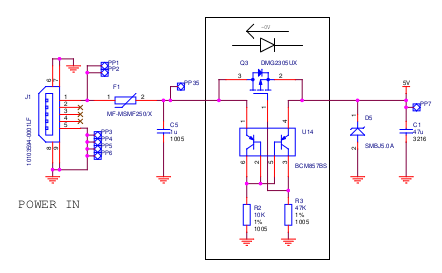
雖然自樹莓派 B+ 以來,基金會並沒有公開設計的電路圖,或許藉由逆向工程? adafruit 網站有一篇專文介紹《 Power Supply 》也許可以一窺堂奧︰
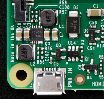
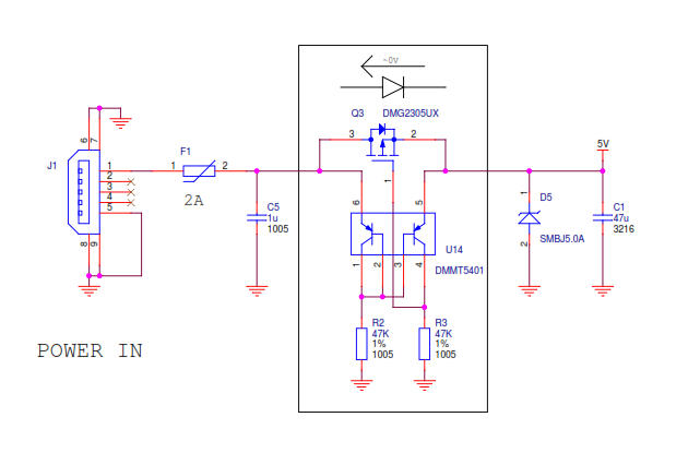
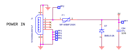
There’s still the microUSB jack on the left, and the 1A fuse has been upgraded to a 2A fuse. There’s also a DMG2305UX P-Channel MOSFET. This acts as a polarity protection switch but is much lower ‘drop-out’ than a diode. It has only 52mΩ resistance so @ 2A its about 0.1V voltage drop. Most diodes would be at least 0.5V.
To the right is a protection TVS diode (D5 part #SMBJ5) which protects from over-voltages.
在那篇文章裡沒有提到的是《 Under-voltage warnings 》︰
The B+ has an under voltage detect trigger which results in the power led going off when voltage drops below about 4.65V. The signal is also available on a gpio line (GPIO35).
……
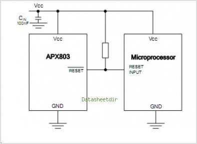
電壓監督
這有什麼重要的嗎?假使說合理的推測︰樹莓派 2B 的電源設計相同於 B+ ,那麼『挑剔 SD 卡』是否與此相關的呢??畢竟如果『電源不給力』,能夠『跑得好』耶!!
─── 摘自《當真電源惹的禍??《上》》
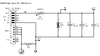
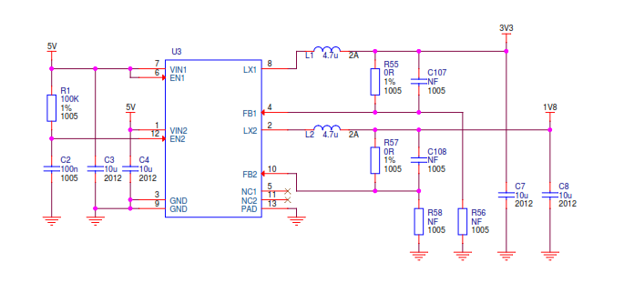
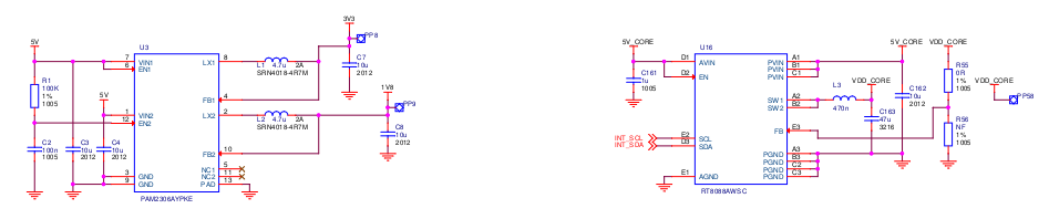
【Raspberry Pi 3B 電源】
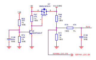
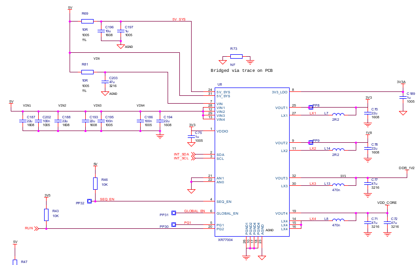
【Raspberry Pi 3B+ 電源】
或將可以『理性判斷』故障容許度
Fault tolerance
Fault tolerance is the property that enables a system to continue operating properly in the event of the failure (or one or more faults within) some of its components. If its operating quality decreases at all, the decrease is proportional to the severity of the failure, as compared to a naively designed system in which even a small failure can cause total breakdown. Fault tolerance is particularly sought after in high-availability or life-critical systems. The ability of maintaining functionality when portions of a system break down is referred to as graceful degradation.[1]
A fault-tolerant design enables a system to continue its intended operation, possibly at a reduced level, rather than failing completely, when some part of the system fails.[2] The term is most commonly used to describe computer systems designed to continue more or less fully operational with, perhaps, a reduction in throughput or an increase in response time in the event of some partial failure. That is, the system as a whole is not stopped due to problems either in the hardware or the software. An example in another field is a motor vehicle designed so it will continue to be drivable if one of the tires is punctured, or a structure that is able to retain its integrity in the presence of damage due to causes such as fatigue, corrosion, manufacturing flaws, or impact.
Within the scope of an individual system, fault tolerance can be achieved by anticipating exceptional conditions and building the system to cope with them, and, in general, aiming for self-stabilization so that the system converges towards an error-free state. However, if the consequences of a system failure are catastrophic, or the cost of making it sufficiently reliable is very high, a better solution may be to use some form of duplication. In any case, if the consequence of a system failure is so catastrophic, the system must be able to use reversion to fall back to a safe mode. This is similar to roll-back recovery but can be a human action if humans are present in the loop.
合宜之範圍乎?