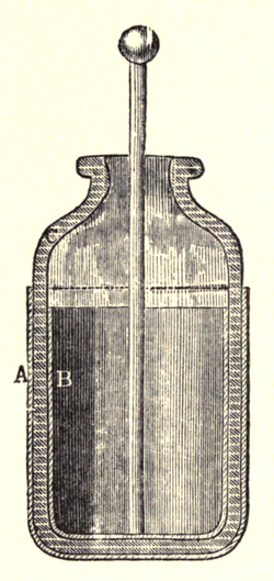
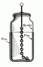
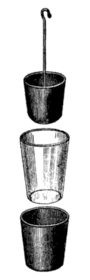
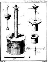
或許在一七四五年代,『電』是一種『時髦』的玩意兒,是科學的『前衛』概念。以至於德國的克拉斯特主教 Ewald Georg von Kleist 也著手於研究『如何儲存』大量的電荷,他將插著鐵釘的玻璃瓶接到了靜電產生器,偶然發現了如此可以暫時的儲存電荷,並且之後還可以再將其傳導出來,這成為了有記錄的第一個『電容瓶』。不過這個電容瓶並不是非常的有名,也許當作一項新的研究成果,那時的技術還不夠成熟。直到一七四六年,一位來自荷蘭的物理學家彼得‧范‧穆森布羅克 Pieter van Musschenbroek,當年他在『萊頓』大學任教時製作出了一個和克拉斯特主教的電容瓶『構造』和『原理』十分相似但是『形狀』不太一樣『電容器』。由於穆森布羅克所製作出來的電容器比電容瓶更加容易攜帶,且易於與其他的機械組裝,並能隨著不同的狀況作調整以適應不同的使用環境。此後電容器開始廣為流傳,因而『萊頓瓶』Leyden jar 之名也就如此而來。當時人們普遍都相信萊頓瓶中的電荷是儲存在瓶內的水裡,並不是在瓶身的玻璃上,一直要等到美國的班傑明‧富蘭克林證明了其電荷確實是儲存在玻璃上的!!
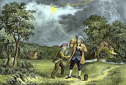
那一位放風箏追雷電又發明『避雷針』的美國著名政治家與科學家班傑明‧富蘭克林 Benjamin Franklin,是一位走在電學最前端的專家,他認為電的單流體理論比較正確。富蘭克林『想像』電儲存於所有物質中,並且通常處於『平衡狀態』,然而摩擦動作會使得電從一個物體流動至另一個物體。因而他認為累積的電是儲存於萊頓瓶的玻璃中,是用絲巾摩擦玻璃而使得電從絲巾流動至玻璃,這流動形成了『電流』。他假想電量『低於平衡』的物體載有『負的電量』 ,電量『高於平衡』的物體攜載『正的電量』。富蘭克林也『任意』指定『玻璃電為正電』,具有多餘的電;而『琥珀電為負電』,缺少了不足的電。與他同時期的英國科學家威廉‧沃森 William Watson 也得到了同樣的結論。一七四七年,富 蘭克林假設在一個『孤立系統』內,總電荷量是恆定的,這稱為『電荷守恆定律』 。富蘭克林一時的任意『指定』,造成了今天『電流的方向』是『正電荷』從『正極流向負極』的『約定』!以至於說到事實上是『電子』的流動時,反而還得用『電子流』的了!!
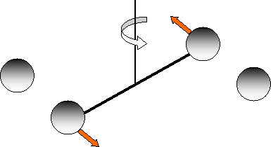
一八七五年法國物理學家夏爾‧奧古斯丁‧德‧庫侖 Charles Augustin de Coulomb 以及英國的自然哲學家約瑟夫‧普利斯特里 Joseph Priestley 各自獨立發明了『扭秤』torsion balance,其中的『扭轉簧』 torsion spring 的『扭轉角』 與『扭力』
與『扭力』 滿足『虎克定律』

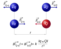
,藉著扭秤,庫侖證實了普利斯特里的基本定律:載有電荷的兩個物體之間的作用力與兩物體『電荷量乘積』成正比,和兩者之間的『距離平方』成反比。這開啟了定量研究『靜電學』 Electrostatics 的時代。之後『電子』的發現以及『原子模型』的歷史,可參見於《【Sonic π】聲波之傳播原理︰共振篇《一》》一文。
大自然中與日常生活裡,有許多靜電現象的例子,像是塑膠袋與手之間的吸引、冬天脫毛衣的劈啪聲、彷彿是自發性的穀倉爆炸與用手接觸電子元件可能的損毀和影印機的運作原理等等。
─── 《【SONIC Π】電聲學導引《二》》
懷古之幽思,重新認識『電容器』!!
Capacitor
.jpg) |
|
| Type | Passive |
|---|---|
| Invented | Ewald Georg von Kleist |
| Electronic symbol | |
 |
|
A capacitor is a passive two-terminal electrical component that stores potential energy in an electric field. The effect of a capacitor is known as capacitance. While some capacitance exists between any two electrical conductors in proximity in a circuit, a capacitor is a component designed to add capacitance to a circuit. The capacitor was originally known as a condenser or condensator.[1] The original name is still widely used in many languages, but not in English.
The physical form and construction of practical capacitors vary widely and many capacitor types are in common use. Most capacitors contain at least two electrical conductors often in the form of metallic plates or surfaces separated by a dielectric medium. A conductor may be a foil, thin film, sintered bead of metal, or an electrolyte. The nonconducting dielectric acts to increase the capacitor’s charge capacity. Materials commonly used as dielectrics include glass, ceramic, plastic film, paper, mica, and oxide layers. Capacitors are widely used as parts of electrical circuits in many common electrical devices. Unlike a resistor, an ideal capacitor does not dissipate energy.
When two conductors experience a potential difference, for example, when a capacitor is attached across a battery, an electric field develops across the dielectric, causing a net positive charge to collect on one plate and net negative charge to collect on the other plate. No current actually flows through the dielectric, however, there is a flow of charge through the source circuit. If the condition is maintained sufficiently long, the current through the source circuit ceases. However, if a time-varying voltage is applied across the leads of the capacitor, the source experiences an ongoing current due to the charging and discharging cycles of the capacitor.
Capacitance is defined as the ratio of the electric charge on each conductor to the potential difference between them. The unit of capacitance in the International System of Units (SI) is the farad (F), defined as one coulomb per volt (1 C/V). Capacitance values of typical capacitors for use in general electronics range from about 1 picofarad (pF) (10−12 F) to about 1 millifarad (mF) (10−3 F).
The capacitance of a capacitor is proportional to the surface area of the plates (conductors) and inversely related to the gap between them. In practice, the dielectric between the plates passes a small amount of leakage current. It has an electric field strength limit, known as the breakdown voltage. The conductors and leads introduce an undesired inductance and resistance.
Capacitors are widely used in electronic circuits for blocking direct current while allowing alternating current to pass. In analog filter networks, they smooth the output of power supplies. In resonant circuits they tune radios to particular frequencies. In electric power transmission systems, they stabilize voltage and power flow.[2] The property of energy storage in capacitors was exploited as dynamic memory in early digital computers.[3]
Theory of operation
Overview
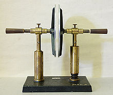
A simple demonstration capacitor made of two parallel metal plates, using an air gap as the dielectric.
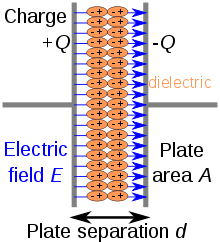
Charge separation in a parallel-plate capacitor causes an internal electric field. A dielectric (orange) reduces the field and increases the capacitance.
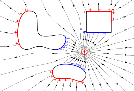
A capacitor consists of two conductors separated by a non-conductive region.[17] The non-conductive region can either be a vacuum or an electrical insulator material known as a dielectric. Examples of dielectric media are glass, air, paper, plastic, ceramic, and even a semiconductor depletion region chemically identical to the conductors. From Coulomb’s law a charge on one conductor will exert a force on the charge carriers within the other conductor, attracting opposite polarity charge and repelling like polarity charges, thus an opposite polarity charge will be induced on the surface of the other conductor. The conductors thus hold equal and opposite charges on their facing surfaces,[18] and the dielectric develops an electric field.
An ideal capacitor is characterized by a constant capacitance C, in farads in the SI system of units, defined as the ratio of the positive or negative charge Q on each conductor to the voltage V between them:[17]

A capacitance of one farad (F) means that one coulomb of charge on each conductor causes a voltage of one volt across the device.[19] Because the conductors (or plates) are close together, the opposite charges on the conductors attract one another due to their electric fields, allowing the capacitor to store more charge for a given voltage than when the conductors are separated, yielding a larger capacitance.
In practical devices, charge build-up sometimes affects the capacitor mechanically, causing its capacitance to vary. In this case, capacitance is defined in terms of incremental changes:

Hydraulic analogy
![]()
In the hydraulic analogy, a capacitor is analogous to a rubber membrane sealed inside a pipe— this animation illustrates a membrane being repeatedly stretched and un-stretched by the flow of water, which is analogous to a capacitor being repeatedly charged and discharged by the flow of charge
In the hydraulic analogy, charge carriers flowing through a wire are analogous to water flowing through a pipe. A capacitor is like a rubber membrane sealed inside a pipe. Water molecules cannot pass through the membrane, but some water can move by stretching the membrane. The analogy clarifies a few aspects of capacitors:
- The current alters the charge on a capacitor, just as the flow of water changes the position of the membrane. More specifically, the effect of an electric current is to increase the charge of one plate of the capacitor, and decrease the charge of the other plate by an equal amount. This is just as when water flow moves the rubber membrane, it increases the amount of water on one side of the membrane, and decreases the amount of water on the other side.
- The more a capacitor is charged, the larger its voltage drop; i.e., the more it “pushes back” against the charging current. This is analogous to the more a membrane is stretched, the more it pushes back on the water.
- Charge can flow “through” a capacitor even though no individual electron can get from one side to the other. This is analogous to water flowing through the pipe even though no water molecule can pass through the rubber membrane. The flow cannot continue in the same direction forever; the capacitor experiences dielectric breakdown, and analogously the membrane will eventually break.
- The capacitance describes how much charge can be stored on one plate of a capacitor for a given “push” (voltage drop). A very stretchy, flexible membrane corresponds to a higher capacitance than a stiff membrane.
- A charged-up capacitor is storing potential energy, analogously to a stretched membrane.
Parallel-plate model
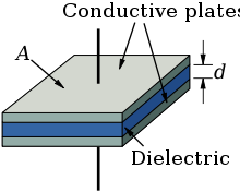
Parallel plate capacitor model consists of two conducting plates, each of area A, separated by a gap of thickness d containing a dielectric.
The simplest model capacitor consists of two thin parallel conductive plates each with an area of  separated by a uniform gap of thickness
  filled with a dielectric with permittivity
  . It is assumed the gap is much smaller than the dimensions of the plates. This model applies well to many practical capacitors which are constructed of metal sheets separated by a thin layer of insulating dielectric, since manufacturers try to keep the dielectric very uniform in thickness to avoid thin spots which can cause failure of the capacitor.
Since the separation between the plates is uniform over the plate area, the electric field between the plates  is constant, and directed perpendicularly to the plate surface, except for an area near the edges of the plates where the field decreases because the electric field lines “bulge” out of the sides of the capacitor. This “fringing field” area is approximately the same width as the plate separation,
  is small compared to the plate dimensions, it is small enough to be ignored. Therefore, if a charge of
  is placed on one plate and
  on the other plate, the charge on each plate will be spread evenly in a surface charge layer of constant charge density
  coulombs per square meter, on the inside surface of each plate. From Gauss’s law the magnitude of the electric field between the plates is
  . The voltage
  between the plates is defined as the line integralof the electric field over a line from one plate to another

The capacitance is defined as  . Substituting above into this equation

Therefore, in a capacitor the highest capacitance is achieved with a high permittivity dielectric material, large plate area, and small separation between the plates.
Since the area of the plates increases with the square of the linear dimensions and the separation increases linearly, the capacitance scales with the linear dimension of a capacitor ( ), or as the cube root of the volume.
A parallel plate capacitor can only store a finite amount of energy before dielectric breakdown occurs. The capacitor’s dielectric material has a dielectric strength Ud which sets the capacitor’s breakdown voltage at V = Vbd = Udd. The maximum energy that the capacitor can store is therefore

The maximum energy is a function of dielectric volume, permittivity, and dielectric strength. Changing the plate area and the separation between the plates while maintaining the same volume causes no change of the maximum amount of energy that the capacitor can store, so long as the distance between plates remains much smaller than both the length and width of the plates. In addition, these equations assume that the electric field is entirely concentrated in the dielectric between the plates. In reality there are fringing fields outside the dielectric, for example between the sides of the capacitor plates, which increase the effective capacitance of the capacitor. This is sometimes called parasitic capacitance. For some simple capacitor geometries this additional capacitance term can be calculated analytically.[20] It becomes negligibly small when the ratios of plate width to separation and length to separation are large.
Energy stored in a capacitor
To increase the charge and voltage on a capacitor, work must be done by an external power source to move charge from the negative to the positive plate against the opposing force of the electric field.[21][22] If the voltage on the capacitor is , the work  required to move a small increment of charge
  from the negative to the positive plate is
  . The energy is stored in the increased electric field between the plates. The total energy stored in a capacitor is equal to the total work done in establishing the electric field from an uncharged state.[23][22][21]

where  is the charge stored in the capacitor, is the voltage across the capacitor, and
  is the capacitance. This potential energy will remain in the capacitor until the charge is removed. If charge is allowed to move back from the positive to the negative plate, for example by connecting a circuit with resistance between the plates, the charge moving under the influence of the electric field will do work on the external circuit.
If the gap between the capacitor plates is constant, as in the parallel plate model above, the electric field between the plates will be uniform (neglecting fringing fields) and will have a constant value  . In this case the stored energy can be calculated from the electric field strength

The last formula above is equal to the energy density per unit volume in the electric field multiplied by the volume of field between the plates, confirming that the energy in the capacitor is stored in its electric field.
Current–voltage relation
The current I(t) through any component in an electric circuit is defined as the rate of flow of a charge Q(t) passing through it, but actual charges—electrons—cannot pass through the dielectric layer of a capacitor. Rather, one electron accumulates on the negative plate for each one that leaves the positive plate, resulting in an electron depletion and consequent positive charge on one electrode that is equal and opposite to the accumulated negative charge on the other. Thus the charge on the electrodes is equal to the integralof the current as well as proportional to the voltage, as discussed above. As with any antiderivative, a constant of integration is added to represent the initial voltage V(t0). This is the integral form of the capacitor equation:[24]

Taking the derivative of this and multiplying by C yields the derivative form:[25]

The dual of the capacitor is the inductor, which stores energy in a magnetic field rather than an electric field. Its current-voltage relation is obtained by exchanging current and voltage in the capacitor equations and replacing C with the inductance L.