打從一開始以來,樹莓派就種下了『電源』傳聞之因︰
雖然今天樹莓派已廣為流行, 賣了數百萬台. 你依然需要注意選用的電源供應器. 考察 樹莓派的原始設計: 如 Raspberry-Pi-R2.0-Schematics-Issue2.2_027.pdf , 512M Rev.B 上所說, F3 保險絲的電阻大約 是 0.28 Ohms, 一般典型使用約為 700mA, 那壓降為 0.196V. 正如網路上曾說好的樹莓派電源供應器, 輸出電壓為 5.25V, 事實是正為了補償壓降損失而來, 才能使 TP1-TP2 間的電壓接近 5V. 如果再考慮供應電線的阻抗, 以及USB其它裝置的供電, TP1-TP2 間的電壓或許將在 5V +- 5% 區間之外, 以致引發某些 USB 裝置的工作不正常.
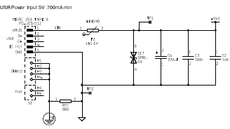
─── 引用《欲善其事, 先利其器: 樹莓派的電源》
雖說其後 B+ 『電源』的設計已經改善,然而還有人使用『充電器』這類的『電源』,由於線材電阻對充電器而言比較不重要,通常都在容許範圍裡。但是電阻過高,使用的電流越大,這個『壓降』會導致樹莓派工作不正常。更不要講又有 USB 埠供電 600 mA 或 1.2 A
max_usb_current=1
config.txt 組構所引起的麻煩︰
Testing & Setting the USB current limiter on the Raspberry Pi B+
One of the features of the new Raspberry Pi B+ is improved power handling – particularly round the USB interfaces. There is a device connected to the power to the USB ports that is quite clever – it controls the power and “soft starts” the peripherals plugged in. This helps to reduce any brown-outs on the main Pi supply, so reducing the chance of the Pi rebooting when you plug in a USB peripheral with the Pi turned on.
Additionally, it can also limit the total current drawn by the USB peripherals. This is 600mA by default, but can be increased to 1.2A via software.
Warning: DO NOT do this on a whim. Only do this if you are absolutely sure that you need to do it!
But if you do need it, then “How?” I hear you ask… Well, simple… There are 2 ways.
The first way is via a new option in /boot/config.txt. Currently you can add:
safe_mode_gpio=4but note that this will become:
max_usb_current=1in subsequent updates.
───
I have the following lines in /boot/config.txt
# uncomment to increase maximum usb current from 600mA to 1200 mA
safe_mode_gpio=4
max_usb_current=1
However I cannot effectively power even an SSD in an external usb drive caddy even with a 2A power supply and 2 USB connections.
This setup works just fine on a B+. Could this be to do with the GPIO software incompatibility problem?
Thanks,
Barnabear.
……
is simply equivalent to
max_usb_current=1
Thats the only reason I can come up with why turning the USB current up doesn’t seem to matter. The circuitry is (i am 99.99% sure) exactly the same, and is working.
───
真是講不清、理還亂,所以現今樹莓派論壇又開始討論︰
Pi 3 power supply & USB cable
I’m a beginner and going to buy a Pi 3
However, I get only a 1.5A cellphone charger… will it works fine?
……
It might work, 2.5A is for extreme conditions – USB hard drive, lots of USB peripherals attached. 1.5A may be enough. I’m using a Pi2 supply with no issues.
But official power supplies are relatively cheap…
……
chrisoh wrote:An article, on Hackaday I think, reported Pi 3 using 720mA as “maximum power consumption at boot” IIRC, so a 1.5A supply should, in theory, be ample for general use I would have thought. I’ll dig out my voltmeter later and have a play with some peripherals and find out some numbers.
Edit:
Hackaday article: http://hackaday.com/2016/03/01/pi-3-ben … e-is-true/
Amended 750mA to 720mA and “idle” to “maximum power consumption at boot”
The 1.5A charger is probably still marginal. The “power budget” for Pi3B was posted as: 1A for the SoC/RAM, 0.3A for WiFi/BT, and 1.2A for full powered to USB. If the increased USB power is NOT selected, then the expected max current would be 1.9A and a good 2A supply would cover it. At 1.5A, it’d be a good idea to disable the WiFi and BT modules as well as not trying to drive the SoC all out, or only use very low power USB devices. Alternatively, leave BT active for wireless keyboard and mouse and don’t use *any* USB devices.
It would be an interesting exercise to see how low you can hold the input current without imposing outrageous limits on what you can do with the system.
───
此處典型的開機實測結果 ── 只接 USB 鍵盤、滑鼠 ── ,類似 MagPi 雜誌文本內容一般︰
Raspberry Pi 3 is out now! Specs, benchmarks & more

Power draw
You can’t get extra performance without a few sacrifices. The Pi 3 draws the most power of the test group, but its extra performance means it spends more time at idle. Those looking for maximum battery life should look at the Model A+ or the Pi Zero as an alternative.
───
作者不知樹莓派官網建議的 5V/2.5A 是否分配為傳聞所說的
1A SoC/RAM
0.3A WiFi/BT
1.2A USB ※ max_usb_current=1
,不過認為這是合理的規劃。
假使遭遇『不開機』的狀況,首先拔除所有 USB 的裝置,使用預設的組構檔 config.txt ,確認是否能夠開機?若是不行,那麼大概就是『電源』的問題了!若是說『電源』的 V/A 標示值應該沒有問題,那麼就可能是『電源線』之『材質』、『線徑』、『線長』引起的『壓降』產生的!!這時若想要確認只有實際『量測』一途。就像在《音樂播放器之 CD 轉成 mp3《三》上》文本中所說之嘗試驗證 USB DVD 讀寫裝置的電源需求一樣︰
『軟體測試』 software testing 的典型定義是:在特定的環境條件下對指定『程式』進行『種種操作』,藉以發現『程式』的『錯誤』,用此衡量它的『軟體品質』,同時對其是否能夠滿足『設計要求』進行『評估』的一套整體程序。
通常人們認為『軟體測試』比『程式設計』簡單,這或許是誤解了『善攻者』之不易,以至於會有『通過測試』,上線後卻發現『程式』不管用之事。實際上『善守者』才容易是『善攻者』,他深知『攻其所必救』與『固其所難攻』之理。

A Bug’s Life
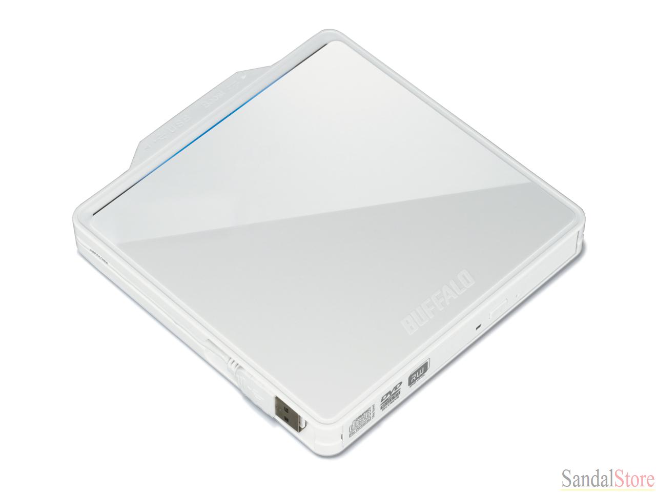
也許可以說『測試』就是用『程式』所允許的『輸入』 Input ,打敗該『程式』之『程序』 Process 之『工藝』。進一步『除錯』,就是嘗試《打開黑箱!!》,找到『原因』並且解決『錯誤』的『活動』。因此於『設計程式』之前,我們需要先『確定』那些使用在『音樂播放器』之『原型機』上的『設備』和『軟體』都『正確無誤』,以及為將來可能的『變更』預做打算。舉例來說,我們如何測試『 USB DVD 讀寫裝置』呢?從這個裝置有兩個 USB 連接頭來看,它是一種耗電量大於 5V 500mA 的裝置,所以才需要兩個『 USB 埠』來供電。其實這也是作者選擇 B+ 而不是 B 的最主要原因, B+ 有四個 USB 埠以及改良過的供電迴路設計。因此只用
lsusb
Bus 001 Device 007: ID 0411:01dc BUFFALO INC. (formerly MelCo., Inc.)
dmesg | grep sr0
[216848.833462] sr0: scsi3-mmc drive: 8x/24x writer dvd-ram cd/rw xa/form2 cdda tray
[216848.838233] sr 0:0:0:0: Attached scsi CD-ROM sr0
,雖然能夠知道 raspbian 認識這個裝置,並不代表它就能夠正常工作。然而確定一個『裝置』或『系統』的【電源需求】,一般需要長時間以及各種操作樣態下的『消耗功率』量測。事實這是十分困難而且麻煩的事情,所以人們多半僅參考產品之『功率規格』來『確認』這件事。有時當系統發生『時好時壞』的狀況時,這個【電源問題】就成了最難診斷的『疑難』之一,更不要講那些用『電池』供電的系統的了。
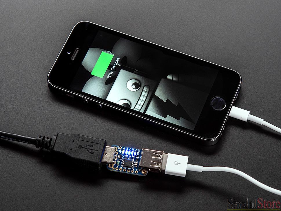
Adafruit USB Power Gauge Mini-Kit
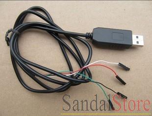
USB TTL RS232 轉換器
後來作者發現 Adafruit 有一款 TTL RS232 界面之迷你的『 USB 埠傳輸功率量測』裝置,如果再加上『USB TTL RS232 轉換器』可以構成一套既便宜又好用的『功率量測』系統。假使輔之以『測試軟體』,可以『自動紀錄』任何一個『 USB 裝置』在各種『工作樣態』下的『功率消耗』。由於它的『量測範圍』可以及於『5V 2A』,因此即使一整個『樹莓派系統』的『消耗功率』大體也可以這麼度量。再者,這個裝置的『資料』輸出格式十分簡單易讀,也就很容易寫『程式』來作『量測數據』處理。在此列出兩種『 USB DVD 讀寫裝置』之『操作狀態』下的消耗功率︰
裝置自起始到閒置 StandBy 量測
cat /dev/ttyUSB0
V: 5.1 I: 491 mA Watts: 2.5
V: 5.1 I: 533 mA Watts: 2.7
V: 5.1 I: 463 mA Watts: 2.4
V: 5.1 I: 521 mA Watts: 2.7
V: 5.1 I: 485 mA Watts: 2.5
V: 5.1 I: 483 mA Watts: 2.5
V: 5.1 I: 479 mA Watts: 2.5
V: 5.1 I: 507 mA Watts: 2.6
V: 5.1 I: 473 mA Watts: 2.4
V: 5.1 I: 515 mA Watts: 2.6
V: 5.1 I: 471 mA Watts: 2.4
V: 5.1 I: 454 mA Watts: 2.3
V: 5.2 I: 351 mA Watts: 1.8
V: 5.3 I: 152 mA Watts: 0.8
V: 5.3 I: 155 mA Watts: 0.8
V: 5.3 I: 148 mA Watts: 0.8
V: 5.3 I: 156 mA Watts: 0.8
V: 5.3 I: 150 mA Watts: 0.8
V: 5.2 I: 152 mA Watts: 0.8
V: 5.3 I: 150 mA Watts: 0.8
V: 5.3 I: 156 mA Watts: 0.8
V: 5.3 I: 146 mA Watts: 0.8
V: 5.3 I: 158 mA Watts: 0.8
V: 5.3 I: 160 mA Watts: 0.8
V: 5.3 I: 154 mA Watts: 0.8
裝置從閒置到播放 CD 量測
cat /dev/ttyUSB0
V: 5.3 I: 155 mA Watts: 0.8
V: 5.3 I: 156 mA Watts: 0.8
V: 5.3 I: 146 mA Watts: 0.8
V: 5.3 I: 153 mA Watts: 0.8
V: 5.1 I: 441 mA Watts: 2.2
V: 4.9 I: 826 mA Watts: 4.0
V: 5.1 I: 445 mA Watts: 2.3
V: 5.1 I: 493 mA Watts: 2.5
V: 5.1 I: 461 mA Watts: 2.4
V: 4.9 I: 461 mA Watts: 2.3
V: 5.1 I: 469 mA Watts: 2.4
V: 5.1 I: 493 mA Watts: 2.5
V: 4.8 I: 971 mA Watts: 4.7
V: 4.8 I: 1022 mA Watts: 4.9
V: 4.8 I: 1022 mA Watts: 5.0
V: 5.0 I: 749 mA Watts: 3.8
V: 4.9 I: 814 mA Watts: 4.0
V: 4.9 I: 837 mA Watts: 4.1
V: 4.9 I: 761 mA Watts: 3.8
V: 5.0 I: 755 mA Watts: 3.7
V: 5.0 I: 821 mA Watts: 4.1
V: 4.9 I: 749 mA Watts: 3.7
V: 5.0 I: 769 mA Watts: 3.8
V: 4.9 I: 797 mA Watts: 3.9
V: 5.0 I: 769 mA Watts: 3.8
V: 4.9 I: 799 mA Watts: 3.9
V: 4.9 I: 814 mA Watts: 4.0
V: 5.0 I: 785 mA Watts: 3.9
V: 5.0 I: 761 mA Watts: 3.8
V: 5.0 I: 701 mA Watts: 3.5
V: 4.9 I: 751 mA Watts: 3.7
V: 4.9 I: 755 mA Watts: 3.7
V: 5.0 I: 725 mA Watts: 3.6
V: 5.0 I: 784 mA Watts: 3.9
V: 4.9 I: 705 mA Watts: 3.5
V: 5.0 I: 769 mA Watts: 3.8
V: 4.9 I: 763 mA Watts: 3.8
V: 4.9 I: 717 mA Watts: 3.5
V: 4.9 I: 804 mA Watts: 4.0
V: 5.0 I: 715 mA Watts: 3.6
V: 4.9 I: 811 mA Watts: 4.0
V: 4.9 I: 789 mA Watts: 3.9
由此我們可以知道,這一個『 USB DVD 讀寫裝置』的消耗功率『變化很大』,假使思考『可靠性設計』的問題,我們需要明白『最大瞬間功率』 ── 紅色數據 ── 的需求,否則可能的系統『不穩定性』就會暗藏其中,日後當系統出狀況時,也許很難追查『原因』。讀者自當可以發現 『 USB 埠傳輸功率量測』裝置的『資料輸出格式』真很『簡潔清楚』的吧!