來知德《周易集註》
䷗ 復 震下坤上
復者,來復也。自五月一陰生後,陽一向在外,至十月變坤,今冬至復來反還于內,所以名復也。《序卦》「物不可以終盡剝,窮上反下,故受之以復」,所以次剝。
復,亨,出入无疾,朋來无咎,反復其道,七日來復,利有攸往。
先言出而後言入者,程子言:語順是也。出者剛長也,入者剛反也 ,疾者遽迫也。言出而剛長之時,自一陽至五陽,以漸而長,是出之時未嘗遽迫也。入而剛反之時,五月一陰生,九月之剝,猶有一陽,至十月陽變,十一月陽反,以漸而反,是入之時,未嘗遽迫也 。朋者,陰牽連于前,朋之象也。故豫卦損卦益卦泰卦咸卦,皆因中爻三陽三陰牽連,皆得稱朋也。自外而之內曰來,言陰自六爻之二爻,雖成朋黨而來,然當陽復之時,陽氣上行,以漸而長,亦無咎病也。復之得亨者以此。道猶言路,言剛反而復之道路也。七日來復者,自姤而遯否觀剝坤復,凡七也,即七日得之意。蓋陽極于六,陰極于六,極則反矣,故七日來復也。无疾咎者, 復之亨也。七日來復,復之期也。利有攸往,復之占也。大抵姤復之理,五月一陰生為姤,一陰生于內則陽氣浮而在外矣。至于十月坤,陰氣雖盛而陽氣未嘗息也, 但在外耳,譬之妻雖為主,而夫未嘗亡,故十一月一陽生,曰剛反,反者言反而歸之于內也。十一月一陽生而復 ,一陽生于內則陰氣浮而在外矣。至于四月乾,陽氣 雖盛而陰氣未嘗息也,但在外耳,譬之夫雖為主,而妻未嘗亡,故五月一陰復生 ,天地雖分陰陽,止是一氣,不過一內一外而已。一內一外即一升一沉,一盛一衰, 一代一謝也。消息盈虛,循環無端,所以言剝言復。
雖然一張『小樹林系統』之圖說︰
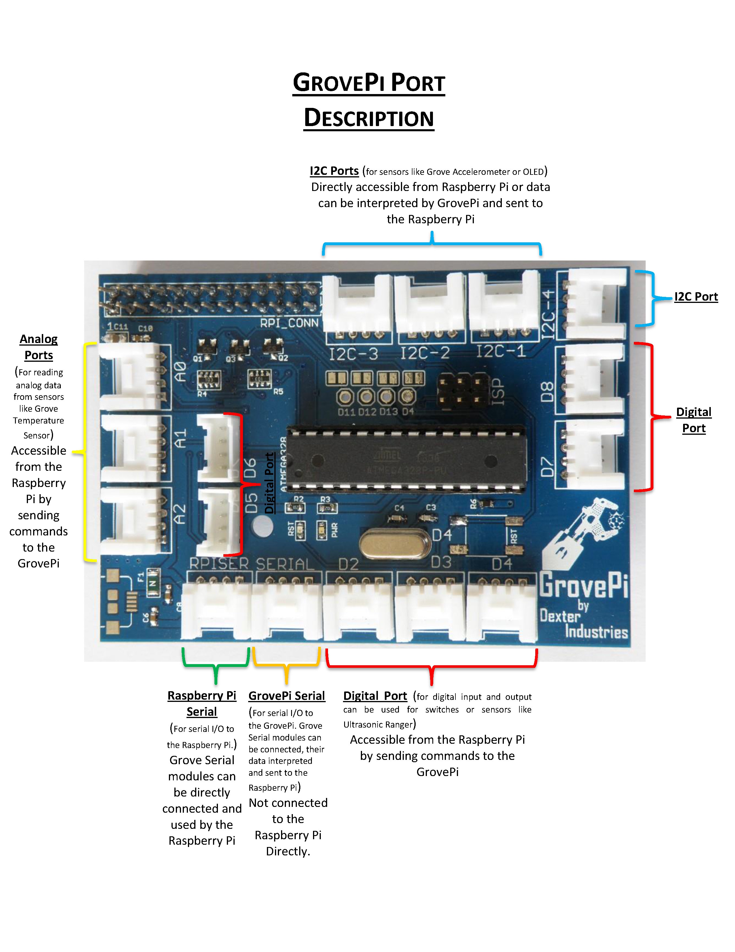
就能清楚表達 Grove System 各種類型的『出入』埠。其中 GrovePi Serial 我們暫且用作了『除錯埠』, I2C 與 Raspberry Pi Serial 通常介接的『感測器』或『使用者界面』元件並非透過『小樹林系統』之韌體直接控制。從這個角度來講,也許此系統最重要的『界面』就由『數位』 Digital 與或『類比』 Analog 所構成的了。
雖說『數位』 和『類比』是『單純』的概念,不過『單純』的事物卻未必『簡單』,類似『純數據』 Pure Data 程式語言裡『箱子』的概念一樣︰
『箱子』 boxes 是一個『奧秘』的觀點,有如《打開黑箱!!》之所言︰
科學追求真理,為的是打開大自然的黑箱;然而真理明白若昭,就是透明的白箱。我們總在求真的旅途上一知半解,努力化灰箱為白箱。如果偵錯就是科學,除錯即求真理,那這一段話用在『偵錯』與『除錯』上來講依然合適。這也說明為什麼人們喜歡用不同的灰度,來表達對『箱內之物』的認識與了解了。
………
千萬不要隨便對
Black box
In science, computing, and engineering, a black box is a device, system or object which can be viewed in terms of its inputs and outputs (or transfer characteristics), without any knowledge of its internal workings. Its implementation is “opaque” (black). Almost anything might be referred to as a black box: a transistor, algorithm, or the human brain.
The opposite of a black box is a system where the inner components or logic are available for inspection, which is most commonly referred to as a white box (sometimes also known as a “clear box” or a “glass box”).
───
□ □ 『性質』與 ○ ○『內涵』隨意假設。最好本著
知之為知之,不知為不知
的精神,『如實』的探索這些『箱子』的『功能』以及其『出入』之連接『方式』,如是或可避免某些『誤解』的吧!無須發生
……
─── 摘自《勇闖新世界︰ W!o《卡夫卡村》變形祭︰品味科學‧教具教材‧【專題】 PD‧箱子世界‧出入》
因為『小樹林系統』韌體的核心是 Arduino ,所以必須深入了解 Arduino 中的︰
Digital Pins
The pins on the Arduino can be configured as either inputs or outputs. This document explains the functioning of the pins in those modes. While the title of this document refers to digital pins, it is important to note that vast majority of Arduino (Atmega) analog pins, may be configured, and used, in exactly the same manner as digital pins.
───
digitalRead()
Description
Reads the value from a specified digital pin, either HIGH or LOW.
Syntax
digitalRead(pin)
Parameters
pin: the number of the digital pin you want to read (int)
Returns
───
digitalWrite()
Description
Write a HIGH or a LOW value to a digital pin.
If the pin has been configured as an OUTPUT with pinMode(), its voltage will be set to the corresponding value: 5V (or 3.3V on 3.3V boards) for HIGH, 0V (ground) for LOW.
If the pin is configured as an INPUT, digitalWrite() will enable (HIGH) or disable (LOW) the internal pullup on the input pin. It is recommended to set the pinMode() to INPUT_PULLUP to enable the internal pull-up resistor. See the digital pins tutorial for more information.
NOTE: If you do not set the pinMode() to OUTPUT, and connect an LED to a pin, when calling digitalWrite(HIGH), the LED may appear dim. Without explicitly setting pinMode(), digitalWrite() will have enabled the internal pull-up resistor, which acts like a large current-limiting resistor.
Syntax
digitalWrite(pin, value)
Parameters
pin: the pin number
Returns
none
─────
Analog Input Pins
A description of the analog input pins on an Arduino chip (Atmega8, Atmega168, Atmega328, or Atmega1280).
A/D converter
The Atmega controllers used for the Arduino contain an onboard 6 channel analog-to-digital (A/D) converter. The converter has 10 bit resolution, returning integers from 0 to 1023. While the main function of the analog pins for most Arduino users is to read analog sensors, the analog pins also have all the functionality of general purpose input/output (GPIO) pins (the same as digital pins 0 – 13).
Consequently, if a user needs more general purpose input output pins, and all the analog pins are not in use, the analog pins may be used for GPIO.
───
analogRead()
Description
Reads the value from the specified analog pin. The Arduino board contains a 6 channel (8 channels on the Mini and Nano, 16 on the Mega), 10-bit analog to digital converter. This means that it will map input voltages between 0 and 5 volts into integer values between 0 and 1023. This yields a resolution between readings of: 5 volts / 1024 units or, .0049 volts (4.9 mV) per unit. The input range and resolution can be changed using analogReference().
It takes about 100 microseconds (0.0001 s) to read an analog input, so the maximum reading rate is about 10,000 times a second.
Syntax
analogRead(pin)
Parameters
pin: the number of the analog input pin to read from (0 to 5 on most boards, 0 to 7 on the Mini and Nano, 0 to 15 on the Mega)
Returns
int (0 to 1023)
Note
If the analog input pin is not connected to anything, the value returned by analogRead() will fluctuate based on a number of factors (e.g. the values of the other analog inputs, how close your hand is to the board, etc.).
───
analogWrite()
Description
Writes an analog value (PWM wave) to a pin. Can be used to light a LED at varying brightnesses or drive a motor at various speeds. After a call to analogWrite(), the pin will generate a steady square wave of the specified duty cycle until the next call to analogWrite() (or a call to digitalRead() or digitalWrite() on the same pin). The frequency of the PWM signal on most pins is approximately 490 Hz. On the Uno and similar boards, pins 5 and 6 have a frequency of approximately 980 Hz. Pins 3 and 11 on the Leonardo also run at 980 Hz.
On most Arduino boards (those with the ATmega168 or ATmega328), this function works on pins 3, 5, 6, 9, 10, and 11. On the Arduino Mega, it works on pins 2 – 13 and 44 – 46. Older Arduino boards with an ATmega8 only support analogWrite() on pins 9, 10, and 11.
The Arduino Due supports analogWrite() on pins 2 through 13, plus pins DAC0 and DAC1. Unlike the PWM pins, DAC0 and DAC1 are Digital to Analog converters, and act as true analog outputs.
You do not need to call pinMode() to set the pin as an output before calling analogWrite().
The analogWrite function has nothing to do with the analog pins or the analogRead function.
Syntax
analogWrite(pin, value)
Parameters
pin: the pin to write to.
value: the duty cycle: between 0 (always off) and 255 (always on).
Returns
nothing
Notes and Known Issues
The PWM outputs generated on pins 5 and 6 will have higher-than-expected duty cycles. This is because of interactions with the millis() and delay() functions, which share the same internal timer used to generate those PWM outputs. This will be noticed mostly on low duty-cycle settings (e.g 0 – 10) and may result in a value of 0 not fully turning off the output on pins 5 and 6.
───
概念、功能、以及運用方法。對於任何不清楚的『術語』,比方說
PWM
The Fading example demonstrates the use of analog output (PWM) to fade an LED. It is available in the File->Sketchbook->Examples->Analog menu of the Arduino software.
Pulse Width Modulation, or PWM, is a technique for getting analog results with digital means. Digital control is used to create a square wave, a signal switched between on and off. This on-off pattern can simulate voltages in between full on (5 Volts) and off (0 Volts) by changing the portion of the time the signal spends on versus the time that the signal spends off. The duration of “on time” is called the pulse width. To get varying analog values, you change, or modulate, that pulse width. If you repeat this on-off pattern fast enough with an LED for example, the result is as if the signal is a steady voltage between 0 and 5v controlling the brightness of the LED.
In the graphic below, the green lines represent a regular time period. This duration or period is the inverse of the PWM frequency. In other words, with Arduino’s PWM frequency at about 500Hz, the green lines would measure 2 milliseconds each. A call to analogWrite() is on a scale of 0 – 255, such that analogWrite(255) requests a 100% duty cycle (always on), and analogWrite(127) is a 50% duty cycle (on half the time) for example.
───
,務須努力探究明白︰
脈衝寬度調變
脈衝寬度調變(英語:Pulse Width Modulation,縮寫:PWM) ,簡稱脈寬調製,是將類比信號 轉換為脈波的一種技術,一般轉換後脈波的週期固定,但脈波的占空比會依類比信號的大小而改變。
在類比電路中,類比信號的值可以連續進行變化,在時間和值的幅度上都幾乎沒有限制,基本上可以取任何實數值,輸入與輸出也呈線性變化。所以在類比電路中,電壓和電流可直接用來進行控制對象,例如家用電器設備中的音量開關控制、採用鹵素燈泡燈具的亮度控制等等。
但類比電路有諸多的問題:例如控制信號容易隨時間漂移,難以調節;功耗大;易受雜訊和環境干擾等等。
與類比電路不同,數位電路是在預先確定的範圍內取值,在任何時刻,其輸出只可能為ON和OFF兩種狀態,所以電壓或電流會通/斷方式的重複脈衝序列加載到類比負載。PWM技術是一種對類比信號電位的數字編碼方法,通過使用高解析度計數器(調製頻率)調製方波的占空比,從而實現對一個類比信號的電位進行編碼。其最大的優點是從處理器到被控對象之間的所有信號都是數位形式的,無需再進行數位類比轉換過程;而且對雜訊的抗干擾能力也大大增強(雜訊只有在強到足以將邏輯值改變時,才可能對數位訊號產生實質的影響),這也是PWM在通訊等信號傳輸行業得到大量應用的主要原因。
類比信號能否使用PWM進行編碼調製,僅依賴帶寬,這即意味著只要有足夠的帶寬,任何類比信號值均可以採用PWM技術進行調製編碼,一般而言,負載需要的調製頻率要高於10Hz,在實際應用中,頻率約在1kHz到200kHz之間。
在信號接收端,需將信號解調還原為類比信號,目前在很多微型處理器內部都包含有PWM控制器模組。
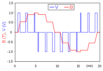
一個例子脈寬調製:供電電壓(藍色)調製為一系列的脈衝產生一個正弦樣磁通密度波形(紅色),在磁路的電磁致動器。平滑的波形由此可以控制的寬度和數目的脈衝調製(每特定週期)
───
Principle

Fig. 1: a pulse wave, showing the definitions of  ,
,  and D.
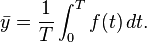
Pulse-width modulation uses a rectangular pulse wave whose pulse width is modulated resulting in the variation of the average value of the waveform. If we consider a pulse waveform  , with period
  , low value , a high value and a duty cycle D (see figure 1), the average value of the waveform is given by:
As is a pulse wave, its value is for 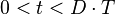 and for
 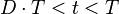 . The above expression then becomes:

This latter expression can be fairly simplified in many cases where  as
as  . From this, it is obvious that the average value of the signal (
 ) is directly dependent on the duty cycle D.
───
Three Ways To Read A PWM Signal With Arduino
PWM (Pulse-Width Modulation) is a modulation technique that controls the width of the pulse based on modulator signal information. PWM can be used to encode information for transmission or to control of the power supplied to electrical devices such as motors.
Generating a PWM signal with an Arduino is quite easy. There is significantly less documentation on how best to read a PWM signal. I needed to read the receiver signals for a remote controlled Quadcopter and after doing some research, I discovered three methods of reading a PWM signal with an Arduino.
───
能夠貫通不同的說法︰
![]() 碼︰有
碼︰有 ![]() 習。兩根母母線,以一千導阻,井通二四與二六 ,古曰︰西金北水關。用二、二十、二百赫茲均任脈衝發西金,以取北水之數論證,訊通此關之法。
習。兩根母母線,以一千導阻,井通二四與二六 ,古曰︰西金北水關。用二、二十、二百赫茲均任脈衝發西金,以取北水之數論證,訊通此關之法。
☿ 答︰『西金』數四、九,既『發』當是『出針』;『北水』一與六,以『取』故為『入針』。『均任』者,平責, duty cycle = dc = 50。『脈衝』者, PWM 也。以『數』『證』之者,證『發數』和『取數』相符。『二』、『二十』、『二百』皆『赫茲』者, Hz 也,全是 PWM 之 frequency 。然而『連續』之『訊號』,考之以『離散』之『讀取』,或可『實證』者,僅『 1 』以及『 0 』平均一周期之『比例』而已。故而『訊通此關之法』之要,在於越能『高速』取值越相合。
☿ ![]() 行︰每每都用母母線!?不知是『母』好用!還是怕我們『不知』用『公』?!☿☺☺
行︰每每都用母母線!?不知是『母』好用!還是怕我們『不知』用『公』?!☿☺☺
欲程式『實證』理論,昨兒乏了,何不改日?…… ☺☿
![]() 訊︰☿ 《古訓》︰井中有仁,切勿落井下石。
訊︰☿ 《古訓》︰井中有仁,切勿落井下石。
─── 摘自《M♪o 之學習筆記本《寅》井井》
當然最好『學而時習之』,入復
亨,出入无疾,朋來无咎,反復其道,七日來復,利有攸往。
之康莊大道也。